Today, we’ll go over the airspeed indicator (ASI). This explanation comes from the FAA textbook Pilot’s Handbook of Aeronautical Knowledge.
The ASI is a sensitive, differential pressure gauge which measures and promptly indicates the difference between pitot (impact/dynamic pressure) and static pressure. These two pressures are equal when the aircraft is parked on the ground in calm air. When the aircraft moves through the air, the pressure on the pitot line becomes greater than the pressure in the static lines. This difference in pressure is registered by the airspeed pointer on the face of the instrument, which is calibrated in miles per hour, knots (nautical miles per hour), or both. (Figure 1)
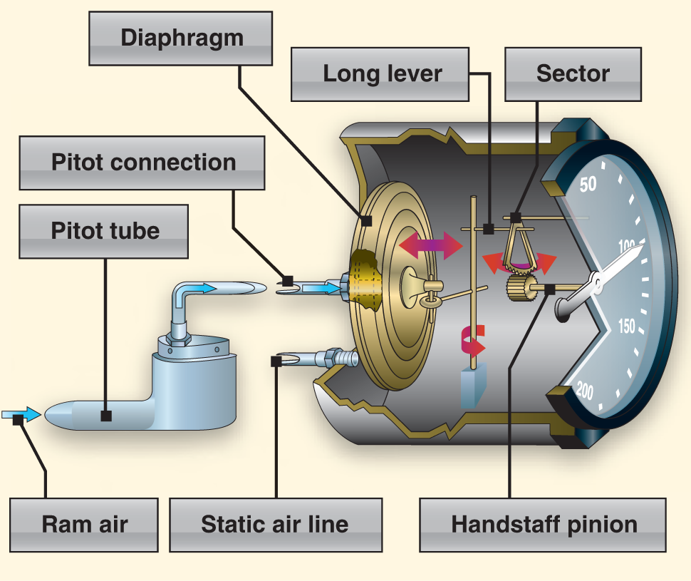
The ASI is the one instrument that utilizes both the pitot, as well as the static system. The ASI introduces the static pressure into the airspeed case while the pitot pressure (dynamic) is introduced into the diaphragm. The dynamic pressure expands or contracts one side of the diaphragm,which is attached to an indicating system. The system drives the mechanical linkage and the airspeed needle.
Just as in altitudes, there are multiple types of airspeeds. Pilots need to be very familiar with each type.
- Indicated airspeed (IAS)—the direct instrument reading obtained from the ASI, uncorrected for variations in atmospheric density, installation error, or instrument error. Manufacturers use this airspeed as the basis for determining aircraft performance. Takeoff, landing, and stall speeds listed in the AFM/POH are IAS and do not normally vary with altitude or temperature.
- Calibrated airspeed (CAS)—IAS corrected for installation error and instrument error. Although manufacturers attempt to keep airspeed errors to a minimum, it is not possible to eliminate all errors throughout the airspeed operating range. At certain airspeeds and with certain flap settings, the installation and instrument errors may total several knots. This error is generally greatest at low airspeeds. In the cruising and higher airspeed ranges, IAS and CAS are approximately the same. Refer to the airspeed calibration chart to correct for possible airspeed errors.
- True airspeed (TAS)—CAS corrected for altitude and nonstandard temperature. Because air density decreases with an increase in altitude, an aircraft has to be flown faster at higher altitudes to cause the same pressure difference between pitot impact pressure and static pressure. Therefore, for a given CAS, TAS increases as altitude increases; or for a given TAS, CAS decreases as altitude increases. A pilot can find TAS by two methods. The most accurate method is to use a flight computer. With this method, the CAS is corrected for temperature and pressure variation by using the airspeed correction scale on the computer. Extremely accurate electronic flight computers are also available. Just enter the CAS, pressure altitude, and temperature, and the computer calculates the TAS. A second method, which is a rule of thumb, provides the approximate TAS. Simply add 2 percent to the CAS for each 1,000 feet of altitude. The TAS is the speed which is used for flight planning and is used when filing a flight plan.
- Groundspeed (GS)—the actual speed of the airplane over the ground. It is TAS adjusted for wind. GS decreases with a headwind, and increases with a tailwind.
Airspeed Indicator Markings
Aircraft weighing 12,500 pounds or less, manufactured after 1945, and certificated by the FAA, are required to have ASIs marked in accordance with a standard color-coded marking system. This system of color-coded markings enables a pilot to determine at a glance certain airspeed limitations that are important to the safe operation of the aircraft. For example, if during the execution of a maneuver, it is noted that the airspeed needle is in the yellow arc and rapidly approaching the red line, the immediate reaction should be to reduce airspeed.
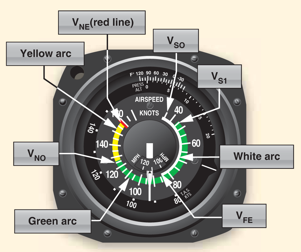
As shown in Figure 2, ASIs on single-engine small aircraft include the following standard color-coded markings:
- White arc—commonly referred to as the flap operating range since its lower limit represents the full flap stall speed and its upper limit provides the maximum flap speed. Approaches and landings are usually flown at speeds within the white arc.
- Lower limit of white arc (VS0)—the stalling speed or the minimum steady flight speed in the landing configuration. In small aircraft, this is the power-off stall speed at the maximum landing weight in the landing configuration (gear and flaps down).
- Upper limit of the white arc (VFE)—the maximum speed with the flaps extended.
- Green arc—the normal operating range of the aircraft. Most flying occurs within this range.
- Lower limit of green arc (VS1)—the stalling speed or the minimum steady flight speed obtained in a specified configuration. For most aircraft, this is the power-off stall speed at the maximum takeoff weight in the clean configuration (gear up, if retractable, and flaps up).
- Upper limit of green arc (VNO)—the maximum structural cruising speed. Do not exceed this speed except in smooth air.
- Yellow arc—caution range. Fly within this range only in smooth air, and then, only with caution.
- Red line (VNE)—never exceed speed. Operating above this speed is prohibited since it may result in damage or structural failure.
As always, be sure to check back Thursday for a post from our CFI.
Featured image by Baptiste Maltaverne from Pixabay.