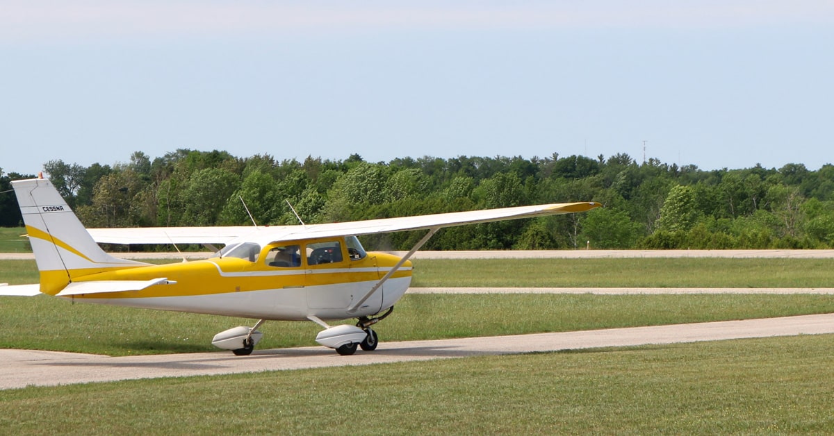
Today’s posts is the first part in a two part series on the pitot-static system and associated pitot-static instruments. We will begin by covering a quick general overview of the pitot-static system as seen in the picture below.
The pitot-static system is responsible for the operation of the airspeed indicator, altimeter, and vertical speed indicator—also known as the pitot-static flight instruments. This is a combined system providing information to the flight instruments through both static air pressure and dynamic pressure due to the motion of the aircraft through the air. Understanding how this system works and properly interrupting failures on the instruments is crucial to the safety of flight.
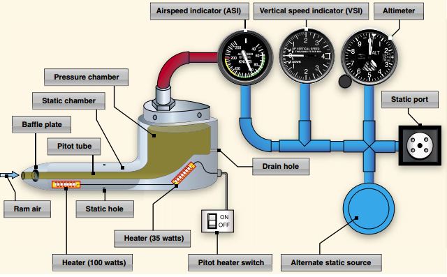
The pitot-tube is that odd shaped mechanism typically hanging below the left wing of the airplane, it is strategically positioned to hang in an area of undisturbed air. Pitot tubes have the unique ability to measure both the static air pressure and dynamic pressure ultimately providing information to the airspeed indicator. On the front end of the pitot-tube you have a small hole allowing ram air to enter the pressure chamber. On the back end you have another small hole; this is known as the drain hole and allows moisture to escape the pressure chamber. You can see how that might be important on a rainy day. During your preflight it is important to check that both of these holes are free and clear of any debris. The majority of all aircraft come with pitot-tube covers to protect from debris entering the pitot-tube while the aircraft sits on the ground. An important feature incorporated into the pitot-tube is pitot heat, this prevents any visible moisture entering the pressure chamber from freezing. The heater is controlled by a switch located on the cockpit panel and should be checked as part of your pre-flight duties. The pitot-tube should be hot to the touch when the pitot heater switch is turned on.
Static ports are located on the aircraft fuselage also in areas of free undisturbed air allowing static air to enter the instruments through small lines connecting the static ports to the instruments (seen in blue in the figure above). As the atmosphere and pressures change the static air is able to move freely in and out. Just like when checking the pitot-tube you should also check the static ports to verify they are free and clear of blockages. Often times when washing an airplane the static port is covered with tape to prevent moisture from entering. Most airplanes are equipped with an alternate static source typically located inside the cockpit. The alternate static source can provide static air pressure in the event your main static port becomes blocked. The airplane will be equipped with a switch or small pull tab to activate the alternate static source, however you should be aware that the pressure inside the cockpit will always be lower than that outside the cockpit. Because of this, when the alternate static is in use, you will observe the following indications:
- Altimeter will indicate a slightly higher than actual altitude.
- Airspeed indicator will show airspeed greater than actual.
- Your vertical speed indicator should momentarily show a climb when the alternate static is activated and then return to normal.
In any event, if all else fails, you can always break the glass on the face of the vertical speed indicator as a way of introducing static air into the system. It is typically chosen to break the glass on the VSI as this is the least important of the three static instruments and when the glass is broke that instrument will be rendered useless.
Next Thursday in Part II we will get into specifics on the three pitot-static instruments and the principal of operation of each.
Feature image by Cjp24, CC BY-SA 4.0 https://creativecommons.org/licenses/by-sa/4.0, via Wikimedia Commons.