On Monday, we learned about the Instrument Landing System and it’s components. Today, I would like to further our discussion and talk about Instrument Approach Procedure Charts. These charts are what depict to pilots how to fly a particular approach into an airport. Many instrument approaches will require the use of an ILS or it’s Localizer component.
With use of the depicted information on an IAP chart a pilot will be assured of terrain and obstruction clearance and runway or airport alignment during approach for landing.
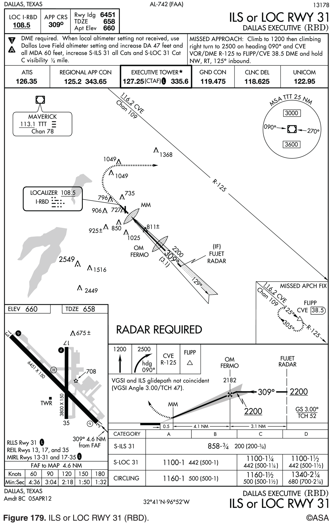
The IAP chart may be divided into four distinct areas: the Plan View, showing the route to the airport; the Profile View, showing altitude and descent information; the Minimums Section, showing approach categories, minimum altitudes, and visibility requirements; and the Airport diagram, showing runway alignments, runway lights, and approach lighting systems.
- The Plan View is that portion of the IAP chart depicted at “A” in the figure below. Atop the IAP chart is the procedure identifications which will depict the A/C equipment necessary to execute the approach, the runway alignment, the name of the airport, the city and state of airport location (See Figure Area #1). An ILS approach, for example, requires the aircraft to have an operable localizer, glide slope, and marker beacon receiver. An LOC/DME approach would require the aircraft to be equipped with both a localizer receiver and distance measuring equipment (DME). If the approach is aligned within 30° of the centerline, the runway number listed at the top of the approach chart means straight-in landing minimums are published for that runway. If the approach course is not within 30° of the runway centerline, an alphabetic code will be assigned to tie IAP identification (for example, NDB-A, VOR-C), indicating that only circle-to-land minimums are published. This would not preclude a pilot from landing straight-in, however, if the pilot has the runway in sight in sufficient time to make a normal approach for landing, and has been cleared to land.
The IAP plan view will list in either upper corner, the approach control, tower, and other communications frequencies a pilot will need. Some listings may include a direction (for example, North 120.2, South 120.8).
The IAP plan view may contain a Minimum Sector Altitude (MSA) diagram. The diagram shows the altitude that would provide obstacle clearance of at least 1,000 feet in the defined sector while within 25 NM of the primary omnidirectional NAVAID; usually a VOR or NDB (See Figure Area #2).
An IAP may include a procedural track around a DME arc to intercept a radial. An arc-to-radial altitude restriction applies while established on that segment of the IAP.
- The Profile View is that portion of the IAP chart depicted at “B” in the Figure. The profile view shows a side view of the procedures. This view includes the minimum altitude and maximum distance for the procedure turn, altitudes over prescribed fixes, distances between fixes, and the missed approach procedure.
- The Minimums Section is that portion of the IAP chart depicted at “C” in the Figure. The categories listed on instrument approach charts are based on aircraft speed. The speed is 1.3 times VS0 at maximum certificated gross landing weight.
- The Aerodrome Data is that portion of the IAP chart which includes an airport diagram, and depicts runway alignments, runway lights, approach lights, and other important information, such as the touchdown zone elevation (TDZE) and airport elevation (See figure area “D”).
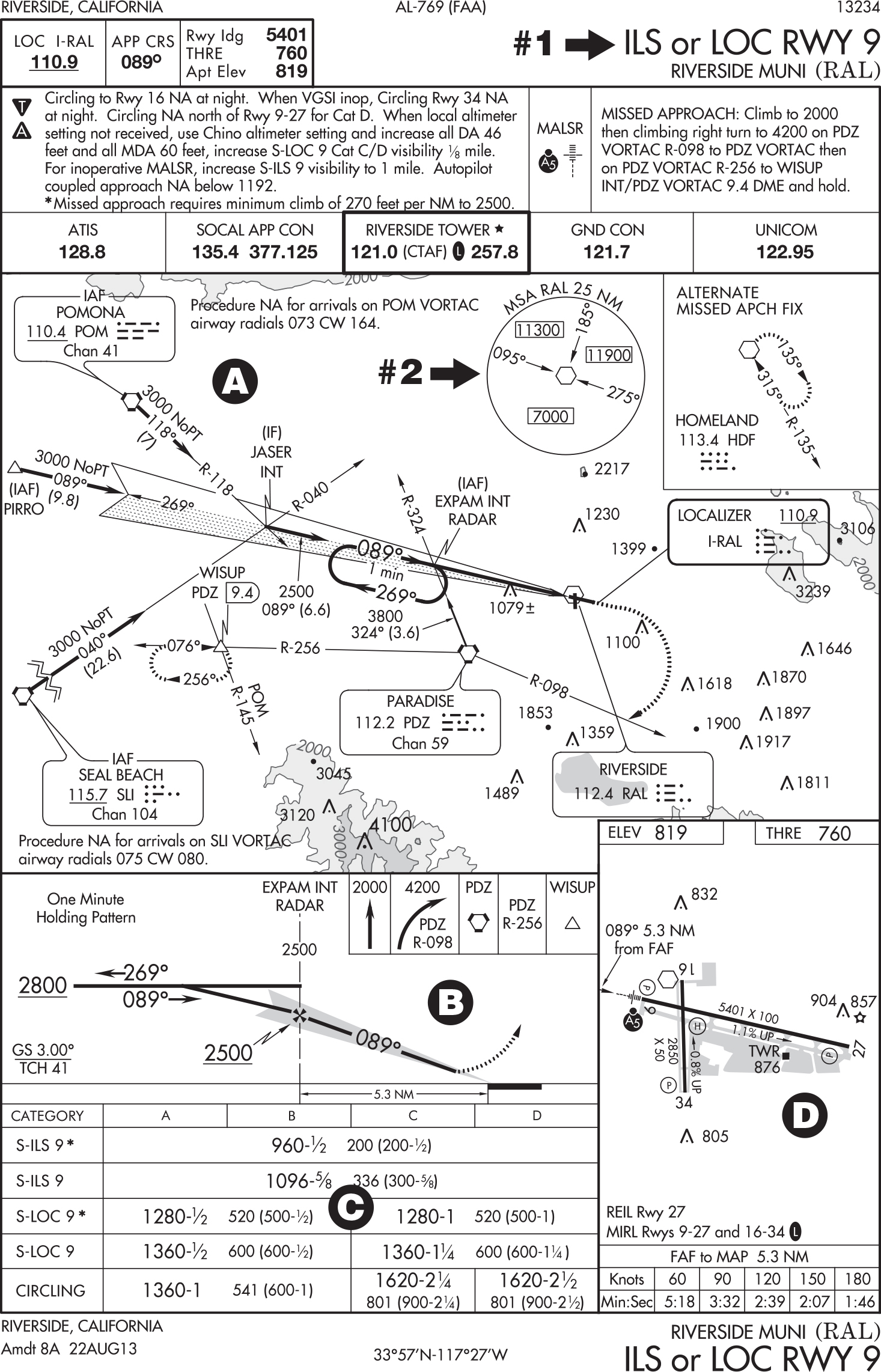
Take a look a the IAP Chart Figure below and see if you can determine the following. Answers will be posted in the comments section.
- What is the minimum equipment required for this approach?
- What are the noted minimum safe altitudes (MSA)?
- What is the decision altitude (DA) if conducting a straight in approach?