Today, we’re featuring an excerpt from The Pilot’s Manual: Instrument Flying. In A Pilot’s Accident Review, author John Lowery recommends that “after about 100 hours of flying with a new private certificate it’s important to the new pilot’s safety and longevity to begin training for an instrument rating.” If you’re a private pilot curious about the IFR rating, a great place to start is our CFI’s “An Introduction to the IFR Rating” as well as other IFR category posts we’ve shared here on the L2FB.
The instrument landing system is known as the ILS. It enables a suitably equipped airplane to make a precision approach to a particular runway. A precision approach is one in which electronic glide slope guidance, as well as tracking guidance, is given. Each ILS is known by the airport and runway it serves, for example, the Lafayette ILS Rwy 10, in Indiana.
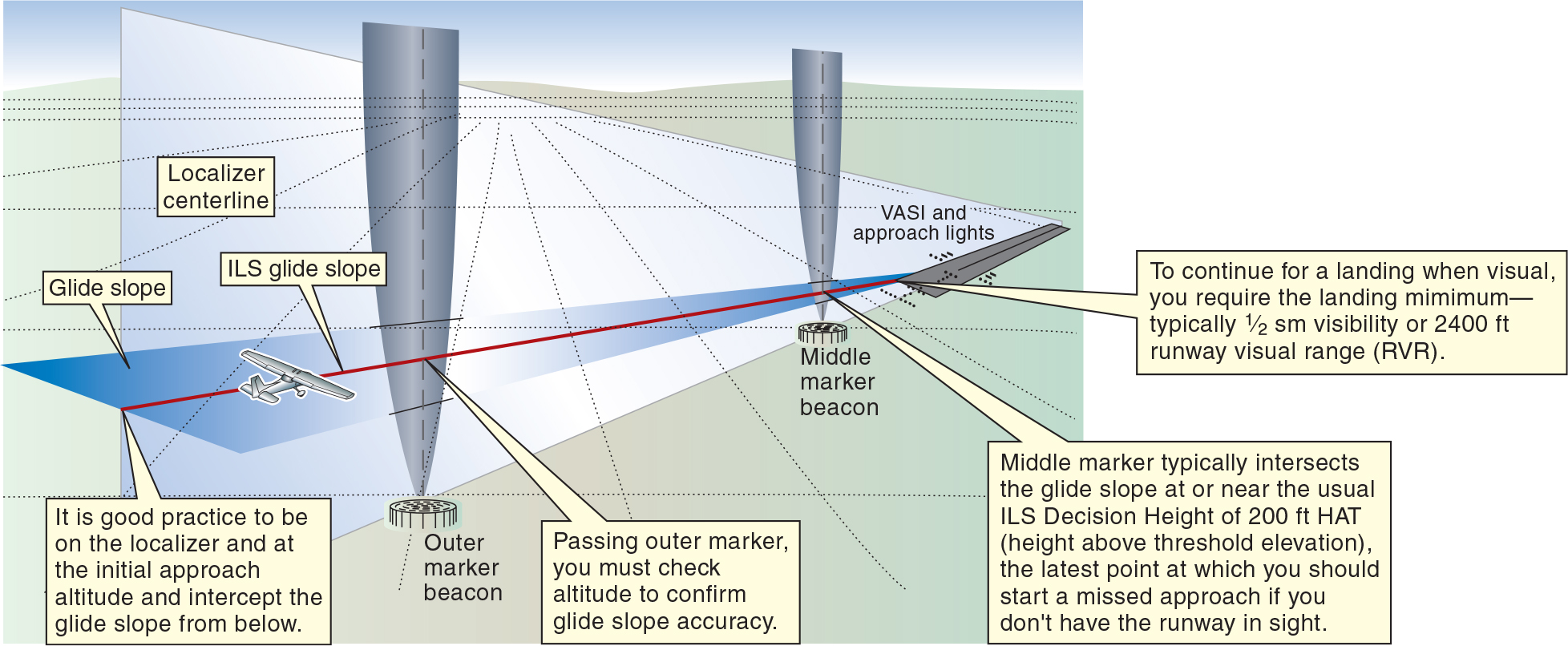
The instrument landing system has four main elements:
- the localizer, which provides course guidance along the extended centerline of the runway (guidance in azimuth left or right of the extended centerline);
- the glide slope, which provides vertical guidance toward the runway touchdown point, usually at a slope of approximately 3° to the horizontal, or 1:20 (vertical guidance above or below the glide slope);
- marker beacons, which provide accurate range fixes along the approach path (usually an outer marker and a middle marker) are provided; and
- approach lights, VASI (visual approach slope indicator), and other lights (touchdown zone lighting, runway lights, etc.) to assist in transitioning from instrument to visual flight.
There may be supplementary NAVAIDs available, including:
- a compass locator (NDB); and
- DME.
The outer marker may be replaced as a range marker on some ILS’s by a compass locator, a DME distance, or an ASR or PAR radar position from ATC. The middle marker, where more accuracy is required, may be replaced as a range marker on some ILS’s by a compass locator or PAR radar position from ATC (but not by a DME distance or ASR radar position). These range markers provide you with an accurate distance fix along the localizer.
A co-located compass locator and outer marker will appear on the approach chart as “LOM.” A co-located compass locator and middle marker will appear on the approach chart as “LMM.”
The ideal flight path on an ILS approach, where the localizer plane and the glide slope plane intersect, is referred to as the glide path. The word glide is really a misnomer carried over from earlier days, since modern airplanes make powered approaches down the glide path, rather than glide approaches. However, the term glide path is still used.
Since ILS approaches will often be made in conditions of poor visibility or at night, there is always associated visual information that can be used once the pilot becomes “visual” (has the runway environment in sight). This may include approach lights leading toward the runway, runway lights, touchdown lights, and centerline lights. Lighting is indispensable for night operations, but it can also be invaluable during daylight hours in conditions of restricted visibility.
There may also be a VASI situated near the touchdown zone to provide visual slope guidance during the latter stages of the approach. This, and other visual information, will assist you in maintaining a stable descent path toward the runway, where you can complete the landing.
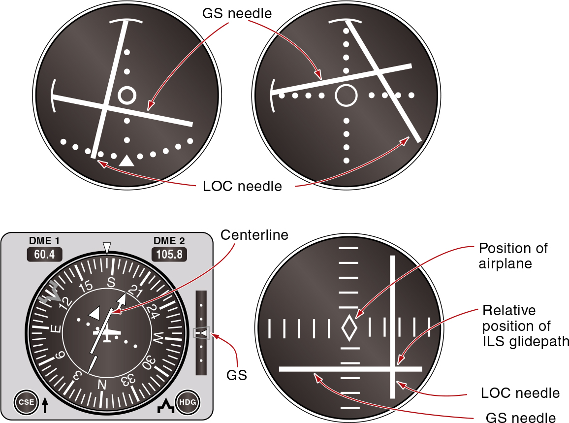
The ILS is selected in the cockpit on the NAV/COM radio. Its cockpit display is usually the same instrument as for the VOR except that, in addition to the vertical localizer needle (CDI) that moves left and right for course guidance, there is a second needle or indicators that come into view. It is horizontal, and is able to move up and down to represent the position of the glide slope relative to the airplane. Some ILS indicators have needles that are hinged and move like wipers, others have needles that move rectilinearly. The airplane may be thought of as the center dot, and the intersection of the needles as the relative position of the glide path.
We’ll have more to share on the ILS, and much more on IFR, in future Monday posts.