Today’s post is excerpted from the second edition of our textbook Aerodynamics for Aviators. This book features extensive illustrations and covers everything from the fundamentals of flight to high-speed flight, and includes an excellent compendium of formulae and equations used at all levels of aviation.
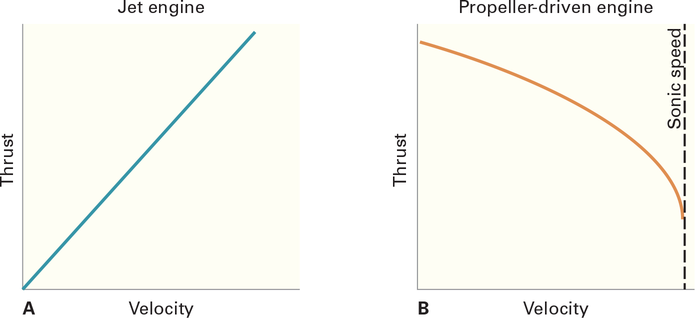
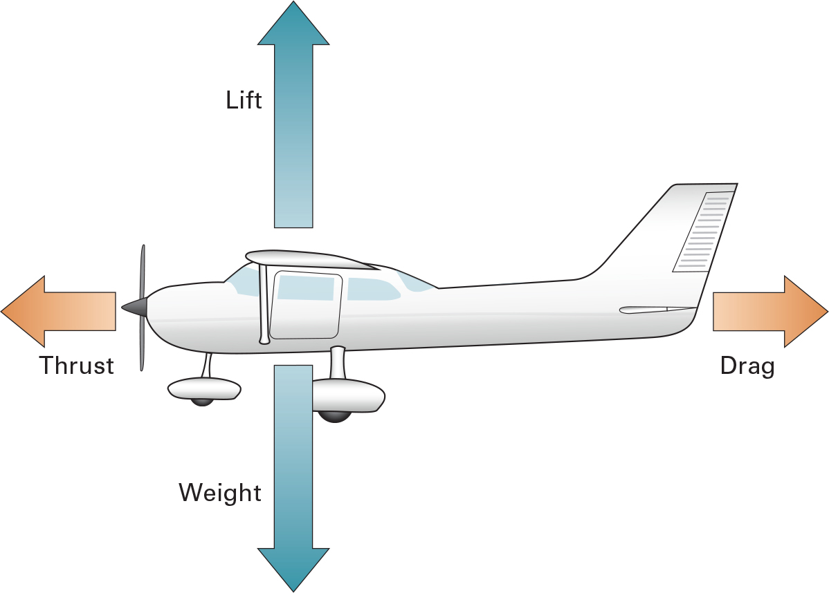
Aircraft aerodynamics involves the interaction of the four forces: lift, weight, thrust, and drag. The first basic issue to understand is the difference between propeller-driven aircraft power and jet engine thrust. Power is what a propeller-driven engine produces; thrust is what a jet engine produces. In a propeller-driven aircraft, the propeller—not the engine—is said to produce thrust. The thrust on a propeller-driven aircraft decreases with an increase in velocity; in a jet aircraft, thrust remains relatively constant with an increase in aircraft velocity.
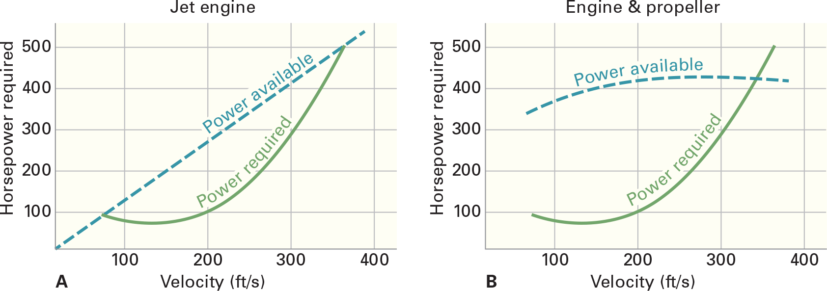
Therefore, the power required curve versus the power available curve for a propeller driven aircraft and a jet aircraft will look different.
jet engine and (B) for a propeller-driven aircraft.
Propeller Efficiency
Propeller efficiency is a measure of how much power is absorbed (transmitted) by the propeller and turned into thrust. In order to understand propeller efficiency, it’s helpful to start with a basic review of propeller principles. Propellers on aircraft consist of two or more blades and a hub. The blades are attached to the hub, and the hub is attached to the crankshaft on a piston-powered aircraft and to a gear reduction box on most turbo-prop aircraft. The propeller is simply a rotating wing that produces lift along the vertical axis. We call this lift force thrust.
Looking at a cross section of the propeller blade, we can see that it is similar to a cross section of an aircraft wing. The top portion of the blade is cambered like the top surface of a wing. The bottom portion is flat like the bottom surface of a wing.
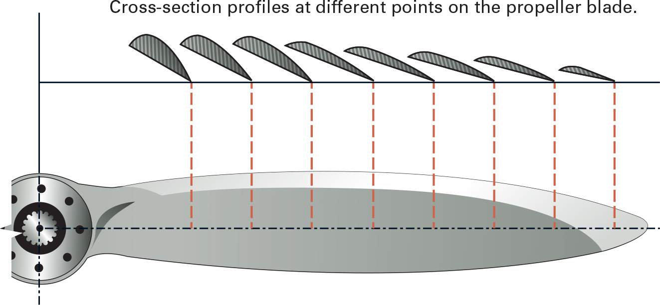
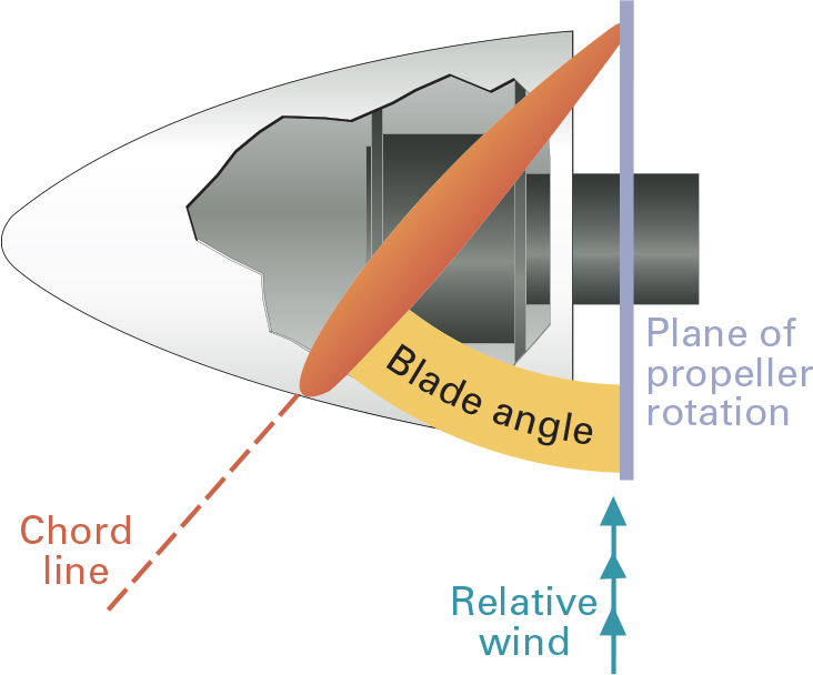
The chord line is an imaginary line drawn from the leading edge of the propeller blade to the trailing edge of the propeller blade. Blade angle, measured in degrees, is the angle between the chord of the blade and the plane of rotation. The pitch of the propeller is usually designated in inches. A “78-52” propeller is 78 inches in length with an effective pitch of 52 inches. The effective pitch is the distance a propeller would move through the air in one revolution if there were no slippage. On a “78-52” propeller this distance would be 52 inches.
There are two types of propellers that can be installed on most general aviation aircraft: a fixed-pitch propeller or a controllable-pitch propeller. The fixed-pitch propeller is at the blade angle that will give it the best overall efficiency for the type of operation being conducted and for which the aircraft was designed. For most aircraft this would be a cruise setting. A controllable-pitch propeller allows the pilot to adjust the blade angle for the different phases of flight. On takeoff and climb out, a low pitch/high RPM setting is used. During cruise flight a high pitch/low RPM setting is generally used.
On the ground with the aircraft in a static condition, the propeller efficiency is very low because each blade is moving through the air at an angle of attack that produces a very low thrust to power ratio. This means that a lot of power is being used to sustain the engine and rotate the propeller while very little thrust is being produced. The propeller, unlike the wing, moves both rotationally and forward (dynamically). The angle at which the relative wind strikes the propeller blade is the AOA. This produces a higher dynamic pressure on the engine side, which in turn is called thrust. Thus thrust is the relationship of propeller AOA and blade angle.
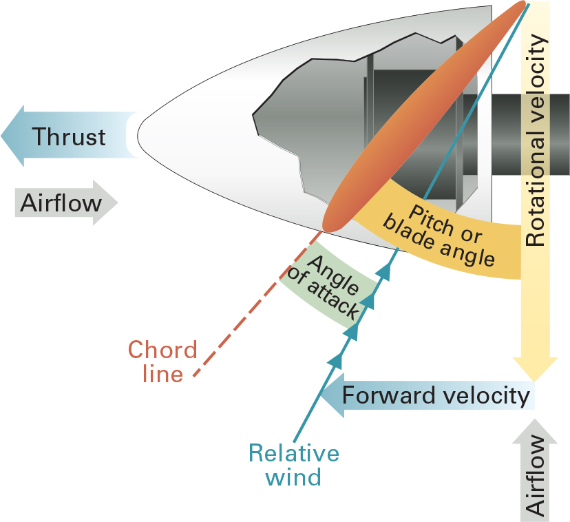
Since an aircraft moves forward through the air, it is important that the pilot understands how forward velocity affects the AOA of the propeller. The figure above shows the propeller in a static condition on the ground. At this point the relative wind is opposing propeller rotation. As forward velocity increases, the relative wind moves closer to the chord line, decreasing the propeller AOA. This can easily be demonstrated in an aircraft with a fixed-pitch propeller by pitching up or down without changing power. When the aircraft is pitched down, RPM will increase as the relative wind moves closer to the chord line and the AOA is decreased. When the aircraft is pitched up, the RPM will decrease as the relative wind moves farther from the chord line and the AOA is increased.
Propeller efficiency is a ratio between thrust horsepower and brake horsepower. Brake horsepower (BHP) is the horsepower actually delivered to the output shaft. Brake horsepower is the actual usable horsepower. Thrust horsepower (THP) is the power that is imparted by the propeller to the air. Propeller efficiency is the relationship between brake horsepower and thrust horsepower. If the BHP of the engine is 200, the THP is less (20–40%). Some power is lost to turn the engine and propeller. Propeller efficiency usually varies between 50 and 80% on light general aviation aircraft.
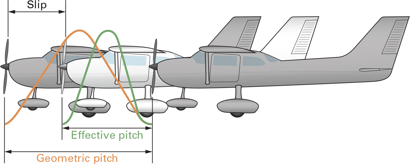
The measure of efficiency is how much a propeller slips in the air. This is measured by the geometric pitch (theoretical) which shows a propeller with no slippage. Effective pitch is the distance that the propeller actually travels.
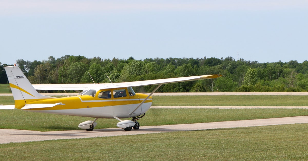
Featured image by TarikVision at stock.adobe.com.