The propeller, the unit which must absorb the power output of the engine, has passed through many stages of development. Today we’ll feature an excerpt introducing the general concepts of a propeller from our recently released book Aircraft Systems for Pilots.
Propeller Principles
The aircraft propeller consists of two or more blades and a central hub to which the blades are attached. Each blade of an aircraft propeller is essentially a rotating wing. As a result of their construction, the propeller blades produce forces that create thrust to pull or push the airplane through the air.
The power needed to rotate the propeller blades is furnished by the engine. The propeller is mounted on a shaft. which may be an extension of the crankshaft on low-horsepower engines; on high-horsepower engines, it is mounted on a propeller shaft which is geared to the engine crankshaft. In either case. the engine rotates the airfoils of the blades through the air at high speeds, and the propeller transforms the rotary motion (power) of the engine into thrust.
The engine supplies brake horsepower through a rotating shaft. and the propeller converts it into thrust horsepower. In this conversion, some power is wasted. For maximum efficiency, the propeller must be designed to keep this waste as small as possible. Since the efficiency of any machine is the ratio of the useful power output to the power input, propeller efficiency is the ratio of thrust horsepower to brake horsepower. The usual symbol for propeller efficiency is the Greek letter η (eta). Propeller efficiency varies from 50% to 87%, depending on how much the propeller “slips.”
THP = BHP × Propeller Efficiency
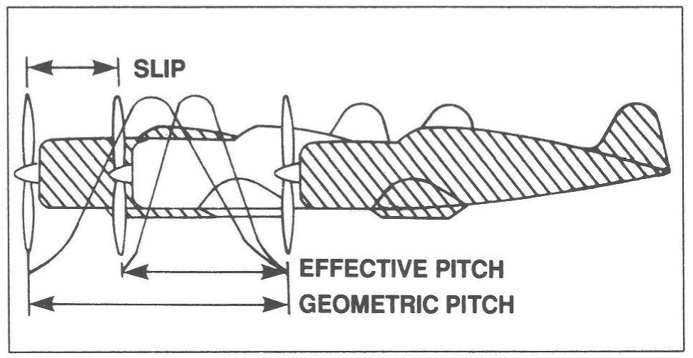
Propeller slip is the difference between the geometric pitch of the propeller and its effective pitch (see figure 1). Geometric pitch is the distance a propeller should advance in one revolution; effective pitch is the distance it actually advances. Thus, geometric or theoretical pitch is based on no slippage, but actual, or effective pitch, recognizes propeller slippage in the air.
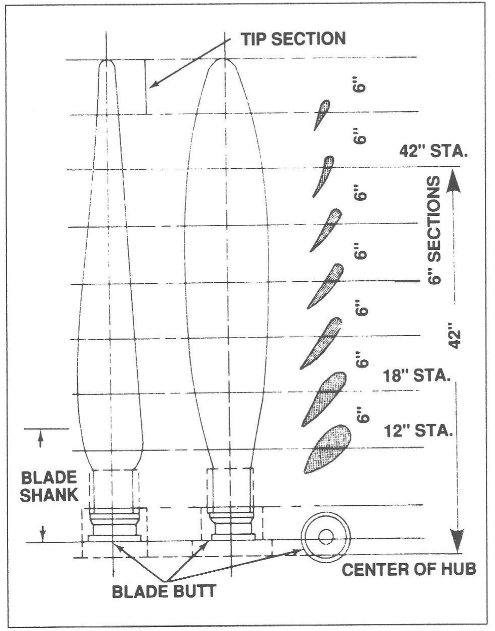
The typical propeller blade can be described as a twisted airfoil of irregular planform. Two views of a propeller blade are shown in figure 2. For purposes of analysis, a blade can be divided into segments, which are located by station numbers in inches from the center of the blade hub. The cross sections of each 6-in. blade segment are shown as airfoils in the right-hand side of figure 2. Also identified in figure 2 are the blade shank and the blade butt. The blade shank is the thick, rounded portion of the propeller blade near the hub, which is designed to give strength to the blade. The blade butt, also called the blade base or root, is the end of the blade that fits in the propeller hub. The blade tip is that part of the propeller blade farthest from the hub, generally defined as the last 6 in. of the blade.
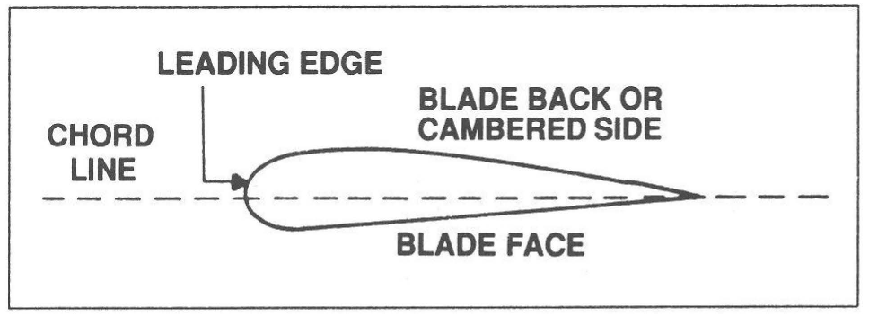
A cross section of a typical propeller blade is shown in figure 3. This section or blade element is an airfoil comparable to a cross section of an aircraft wing. The blade back is the cambered or curved side of the blade, similar to the upper surface of an aircraft wing. The blade face is the flat side of the propeller blade (“facing” the pilot, if the propeller is up front in the tractor position). The chord line is an imaginary line drawn through the blade from the leading edge to the trailing edge. The leading edge is the thick edge of the blade that meets the air as the propeller rotates.
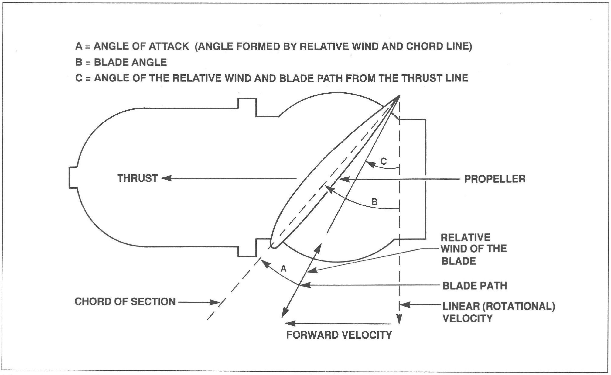
Blade angle, usually measured in degrees, is the angle between the chord line of the blade and the plane of rotation (figure 4). The chord of the propeller blade is determined in about the same manner as the chord of an airfoil. In fact, a propeller blade can be considered as being made up of an infinite number of thin blade elements, each of which is a miniature airfoil section whose chord is the width of the propeller blade at that section. Because most propellers have a flat blade face, pitch is easily measured by finding the angle between a line drawn along the face of the propeller blade and a line scribed by the plane of rotation. Pitch is not the same as blade angle, but, because pitch is largely determined by blade angle, the two terms are often used interchangeably. An increase or decrease in one is usually associated with an increase or decrease in the other.
Forces Acting On The Propeller
A rotating propeller is acted upon by centrifugal, twisting, and bending forces. The principal forces acting on a rotating propeller are illustrated in figure 5.
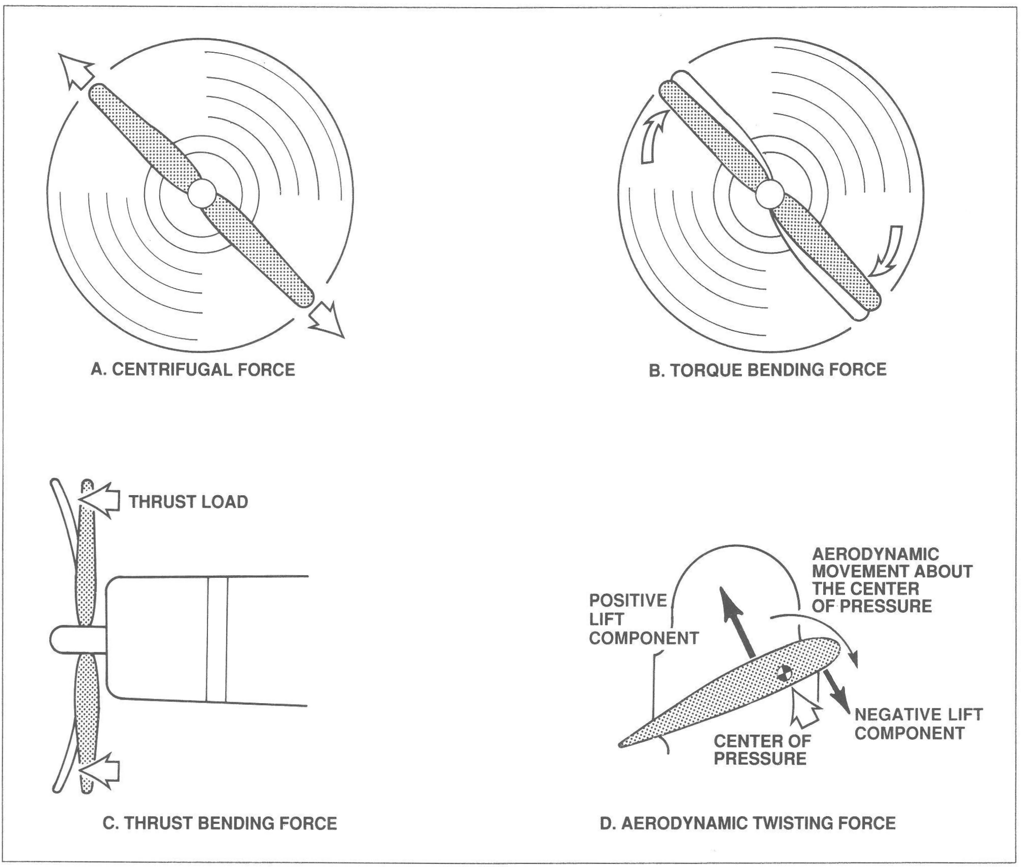
Centrifugal force (A of figure 5) is a physical force that tends to throw the rotating propeller blades away from the hub. Torque bending force (B of figure 5), in the form of air resistance, tends to bend the propeller blades opposite to the direction of rotation. Thrust bending force (C of figure 5) is the thrust load that tends to bend propeller blades forward as the aircraft is pulled through the air. Aerodynamic twisting force (D of figure 5) creates a rotational force (twisting moment) about the center of pressure, causing the blade to tend to pitch to a lower blade angle (streamline).
At high angles of attack this twisting moment is reduced as the center of lift moves forward. At very high blade angles of attack, the blades may exhibit a weak tendency to pitch toward a greater blade angle.
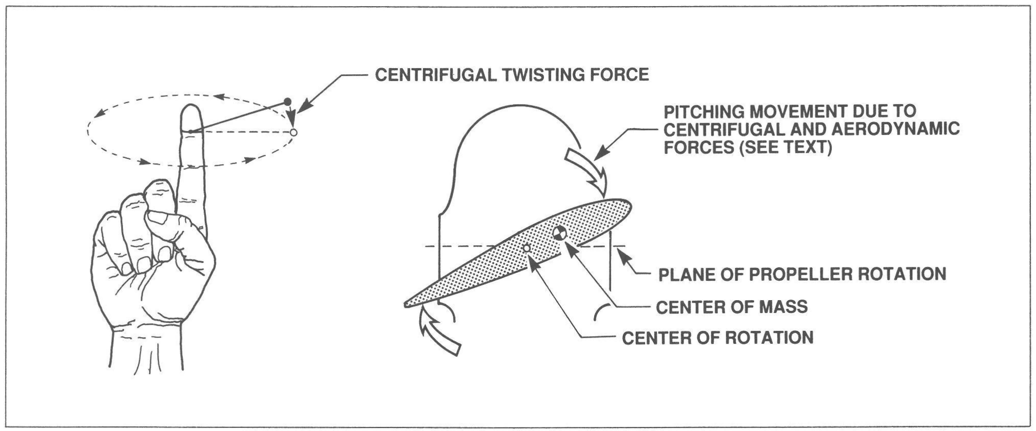
Centrifugal twisting force also twists the blade to flat pitch (unless the blade is counterweighted so its center of mass is behind the center of rotation). This is a strong force at normal propeller speeds. Imagine a string tied to your finger and to a small weight (see figure 6). If the weight is spinning about your finger, the weight will align itself directly in line with the point on your finger where it is tied (reference the plane scribed by the spinning weight). This same force causes the center of mass of the propeller to align itself with the center of rotation on the spin-plane, causing a strong pitch tendency toward minimum blade pitch angle.
A propeller must be capable of withstanding severe stresses, which are greater near the hub, caused by centrifugal force and thrust. The stresses increase in proportion to the RPM. The blade face is also subjected to tension from the centrifugal force and additional tension from the bending. For these reasons, nicks or scratches on the blade may cause very serious consequences.
A propeller must also be rigid enough to prevent fluttering, a type of vibration in which the ends of the blade twist back and forth at high frequency around an axis perpendicular to the engine crankshaft. Fluttering is accompanied by a distinctive noise often mistaken for exhaust noise. The constant vibration tends to weaken the blade and eventually causes failure.
Featured image by KissShot at adobe stock.com.