This Thursday, we’ll pick up where we left off with flight planning last week, but today we have a post on another cockpit navigation aid: the automatic direction finder (ADF). This post is excerpted from the Pilot’s Handbook of Aeronautical Knowledge.
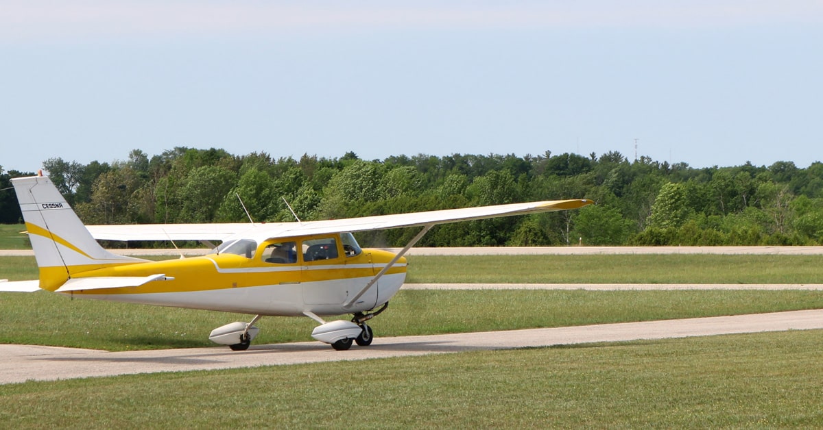
Many general aviation-type aircraft are equipped with ADF radio receiving equipment. To navigate using the ADF, the pilot tunes the receiving equipment to a ground station known as a nondirectional radio beacon (NDB). The NDB stations normally operate in a low or medium frequency band of 200 to 415 kHz. The frequencies are readily available on aeronautical charts or in the A/FD.
All radio beacons except compass locators transmit a continuous three-letter identification in code except during voice transmissions. A compass locator, which is associated with an instrument landing system, transmits a two-letter identification.
Standard broadcast stations can also be used in conjunction with ADF. Positive identification of all radio stations is extremely important and this is particularly true when using standard broadcast stations for navigation.
NDBs have one advantage over the VOR. This advantage is that low or medium frequencies are not affected by line-of-sight. The signals follow the curvature of the Earth; therefore, if the aircraft is within the range of the station, the signals can be received regardless of altitude.
The following table gives the class of NDB stations, their power, and usable range:
| NONDIRECTIONAL RADIO BEACON (NDB) (Usable Radius Distances for All Altitudes) |
||
|---|---|---|
| Class | Power (Watts) | Distance (Miles) |
| Compass Locator | Under 25 | 15 |
| MH | Under 50 | 25 |
| H | 50-1999 | *50 |
| HH | 2000 or more | 75 |
One of the disadvantages that should be considered when using low frequency (LF) for navigation is that low frequency signals are very susceptible to electrical disturbances, such as lightning. These disturbances create excessive static, needle deviations, and signal fades. There may be interference from distant stations. Pilots should know the conditions under which these disturbances can occur so they can be more alert to possible interference when using the ADF.
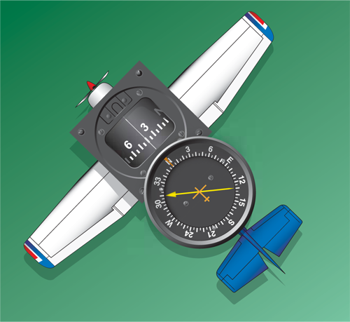
Basically, the ADF aircraft equipment consists of a tuner, which is used to set the desired station frequency, and the navigational display.
The navigational display consists of a dial upon which the azimuth is printed, and a needle which rotates around the dial and points to the station to which the receiver is tuned.
Some of the ADF dials can be rotated to align the azimuth with the aircraft heading; others are fixed with 0° representing the nose of the aircraft, and 180° representing the tail.
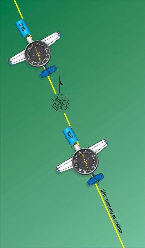
The figure below illustrates terms that are used with the ADF that should be understood by the pilot.
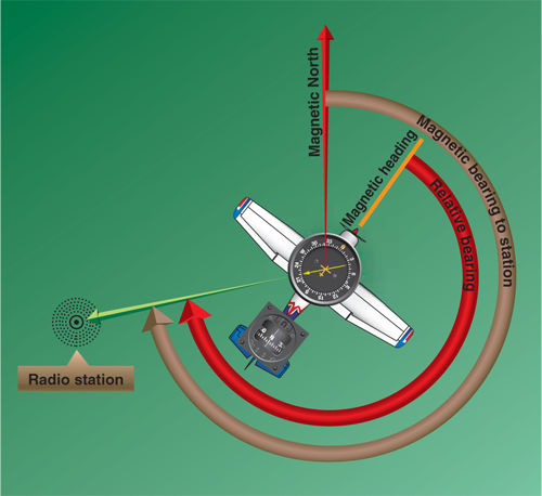
To determine the magnetic bearing “FROM” the station, 180° is added to or subtracted from the magnetic bearing to the station. This is the reciprocal bearing and is used when plotting position fixes. Keep in mind that the needle of fixed azimuth points to the station in relation to the nose of the aircraft. If the needle is deflected 30° to the left for a relative bearing of 330°, this means that the station is located 30° left. If the aircraft is turned left 30°, the needle moves to the right 30° and indicates a relative bearing of 0°, or the aircraft is pointing toward the station. If the pilot continues flight toward the station keeping the needle on 0°, the procedure is called homing to the station. If a crosswind exists, the ADF needle continues to drift away from zero. To keep the needle on zero, the aircraft must be turned slightly resulting in a curved flightpath to the station. Homing to the station is a common procedure, but results in drifting downwind, thus lengthening the distance to the station.
Tracking to the station requires correcting for wind drift and results in maintaining flight along a straight track or bearing to the station. When the wind drift correction is established, the ADF needle indicates the amount of correction to the right or left. For instance, if the magnetic bearing to the station is 340°, a correction for a left crosswind would result in a magnetic heading of 330°, and the ADF needle would indicate 10° to the right or a relative bearing of 010°.
When tracking away from the station, wind corrections are made similar to tracking to the station, but the ADF needle points toward the tail of the aircraft or the 180° position on the azimuth dial. Attempting to keep the ADF needle on the 180° position during winds results in the aircraft flying a curved flight leading further and further from the desired track. To correct for wind when tracking outbound, correction should be made in the direction opposite of that in which the needle is pointing.
Although the ADF is not as popular as the VOR for radio navigation, with proper precautions and intelligent use, the ADF can be a valuable aid to navigation.