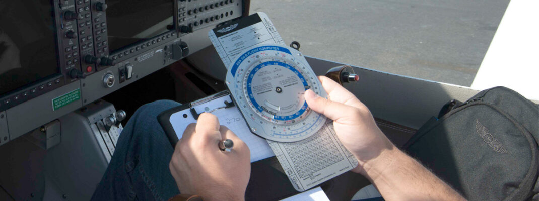
Let’s continue our examination of the E6-B flight computer. As a reminder, an E6-B has two main parts: (1) a circular slide rule side for quick calculations; and (2) a wind side for computing groundspeed and wind correction angle. A previous post discussed the circular slide rule side, and this one will be focused on the wind correction side.
Wind Correction Side
On the E6-B, the wind correction tool is used for vector math problems like the following:
- Determining wind correction angle (WCA)
- Determining groundspeed
- Plotting crosswind/headwind components relative to course
Components on the wind side are (1) the rotating azimuth ring (compass rose) labeled 0°–360°; (2) the True Index (fixed reference mark); (3) the sliding wind grid with parallel lines and centerline; (4) the center grommet/pivot; and (5) knot-spaced horizontal grid lines for measuring wind speed, groundspeed, and drift.
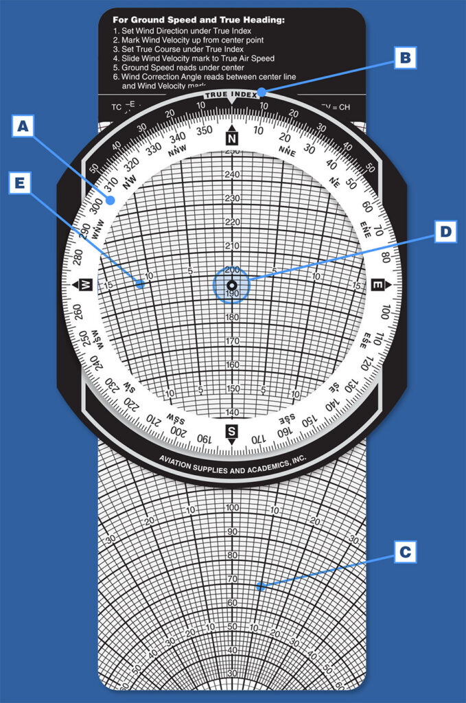
The wind side of the E6-B provides a graphic method for solving trigonometry problems and displaying the results in a practical aviation format. To determine groundspeed and wind correction angle (WCA), you need four inputs: (1) true course, (2) true airspeed, (3) wind direction, and (4) wind velocity.
The winds aloft forecast provides wind direction and velocity. You can measure the true course directly from your sectional chart, and true airspeed can either be converted from indicated airspeed in flight or found in the aircraft performance charts during preflight planning. To use the wind side you’ll need a pencil or dry erase marker to draw on the disk.
How to Use the Wind Correction Side
This side is easier to understand using an example: For a flight with a wind direction of 140° and wind velocity of 10 knots, the airspeed is 120 knots, and the true course is 100°, we’ll use the E6-B to find the groundspeed and wind correction angle.
First, set the wind by rotating the transparent disc until the wind direction (140°) is opposite the True Index marking. Then slide the rectangular card until the center grommet is over the true airspeed (120 knots).
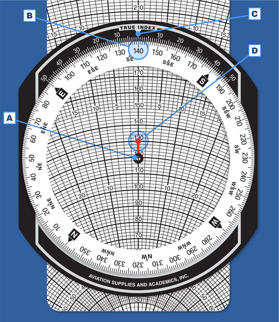
From the grommet, measure upward and place a dot representing the wind velocity using a pencil or erasable marker—some users prefer to draw a line upwards to represent the wind velocity. For a wind velocity of 10 knots you would draw up from 120 to 130 and place a dot on that line (as shown in Figure 2).
Now, rotate the transparent disc to align your true course (100°) with the True Index marking. Notice the arcs marked on the center line, and then slide the rectangular grid up or down until the dot you drew on the transparent disc lies on the arc of your true airspeed (120 knots).
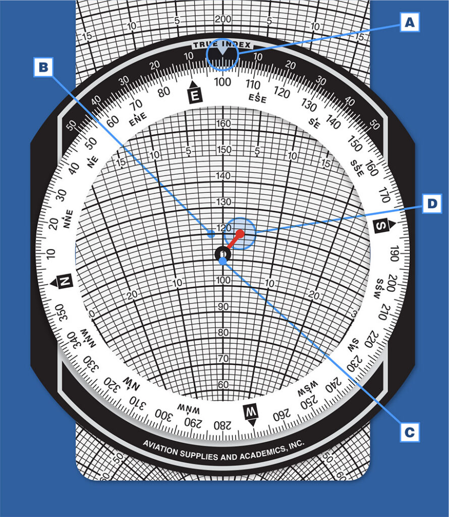
Your groundspeed will be directly below the grommet, which in this case is at 112 knots (each line represents 2 knots). The wind correction angle is the number of degrees the dot lies to the left or right of the center line. Read this carefully by following a line upward or downward to the nearest marking row. In this case, each line represents 2°, and the dot appears 3° to the right of center.
Left wind correction is subtracted, and right wind correction added (−L, +R) to or from true course to determine your true heading. So, in this problem the wind direction and velocity create a quartering headwind from the right resulting in a groundspeed of 112 knots and a true heading of 103° (100° + 3°).
This gets easier with practice. Click here to order your own ASA E6-B, and find ASA’s E6-B tutorial (a STEM-focused teacher’s guide that includes lesson plans) on our website for more wind correction examples.