I am sure you have been waiting all week for Part II of the CFI Brief on the Pitot-Static system. So here it is: today we will get into some of the principals of operation of each of the three pitot-static instruments found in the cockpit: altimeter, vertical speed indicator, and airspeed indicator.
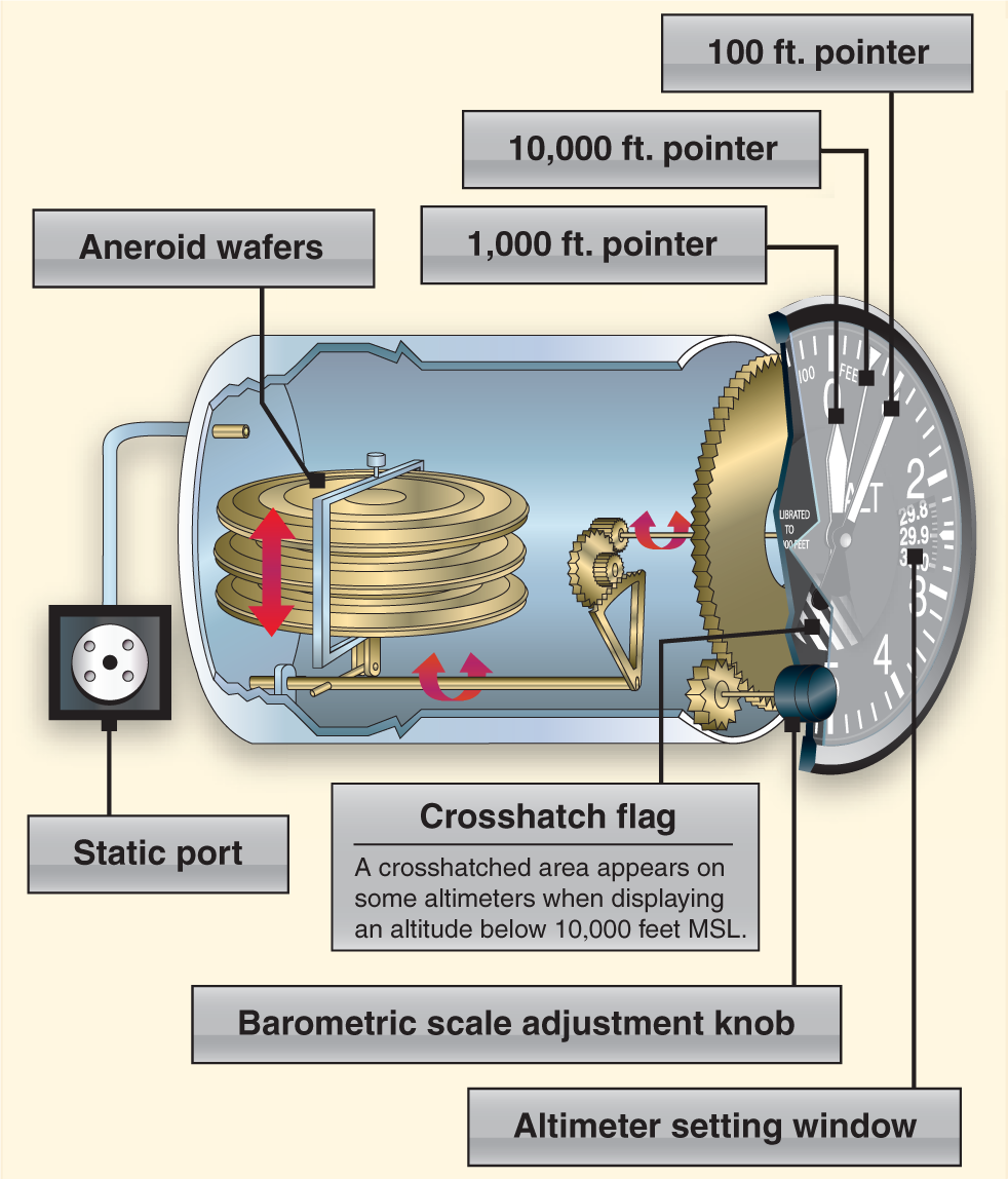
The altimeter measures the height of an aircraft above sea level or a given pressure level by measuring static air pressure introduced through the static port. As the pressure enters through the static port it is able to freely flow through small lines connected to the back of the altimeter box as seen in figure 1 below. The main component of the altimeter is a stack of sealed aneroid wafers that has been set to an internal pressure of 29.92 Hg. These wafers are able to expand and contract as pressure within the instrument box changes. Remember as you go up in altitude pressure decrease allowing the wafers to expand and vice versa, as you decrease in altitude pressure increase contracting the wafers. Next time you drive over a mountain pass take along with you a sealed bag of chips and watch the bag expand as you drive up the pass. Once you get back down the other side the bag will be back to normal. This is essentially the same thing happening inside the altimeter. The aneroid wafers are connected through mechanical linkage to pointers on the face of the instrument that register the pressure presenting it as an altitude indication given in feet.
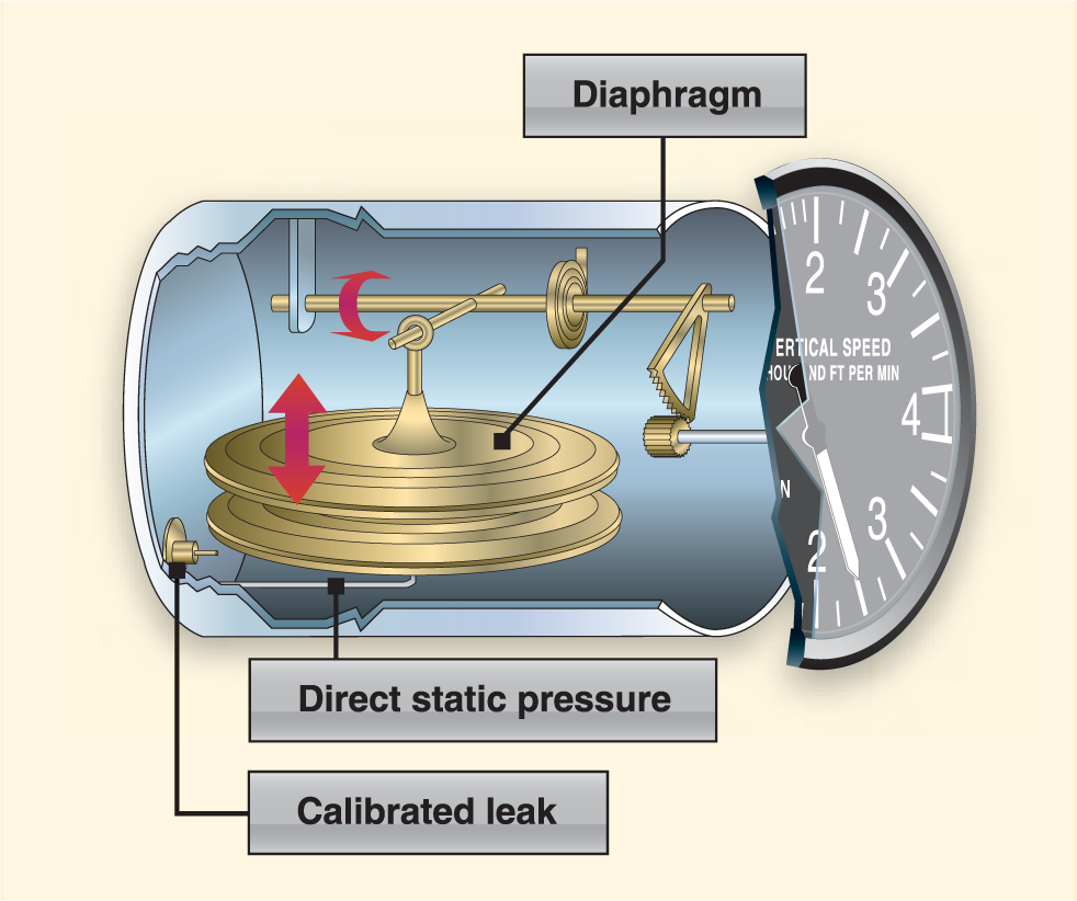
Next up, the vertical speed indicator, as you know this instrument indicates the rate of climb or descent of the aircraft. The VSI is considered to be what’s called a differential pressure instrument, meaning it uses the differences in pressure to indicate whether the aircraft is in a climb or descent. The internal components consist of a diaphragm, calibrated leak orifice, and mechanical linkage. Unrestricted air from the static line enters directly into the diaphragm while static air enters the air tight casing through the calibrated leak. If the aircraft were in level flight or on the ground this pressure would be equal. As the aircraft climbs or descends the pressure inside the diaphragm changes immediately. The case pressure however does not; because of the calibrated leak the pressure inside the instrument casing will remain higher or lower for a period of time. This difference in pressure between the two is what allows the diaphragm to expand and contract and through the mechanical linkage is shown as either a climb or descent on the instrument face.
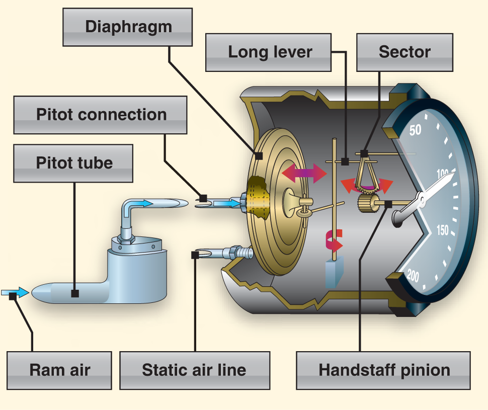
Lastly, we have the airspeed indicator, the only instrument that uses both pitot and static pressure. The ASI measures the difference between pitot and static pressure (impact and dynamic) and registers it as an airspeed shown on the face of the instrument. When the two pressures are equal the airspeed is shown as zero. Ram air entering the pitot-tube is directed though pitot lines to a diaphragm contained within the instrument case (you can see this in figure 3 below). The greater the impact pressure from the pitot-tube the larger the diaphragm expands. Through the static line dynamic pressure enters into the instrument casing surround the diaphragm. As the diaphragm expands and contracts against the differences in pressure it indicates this through mechanical linkage to an indicating needle on the face of the instrument. The greater the pressure differences the higher the indicated airspeed.
This has been such a fun topic to discuss that I thought hey why not add a Part III! So next week, look for the conclusion of the CFI Brief on the pitot-static system, specifically focusing on errors and failures that can occur and how they will be reflected on the instruments. I might even through together a little quiz to test your knowledge so be prepared!
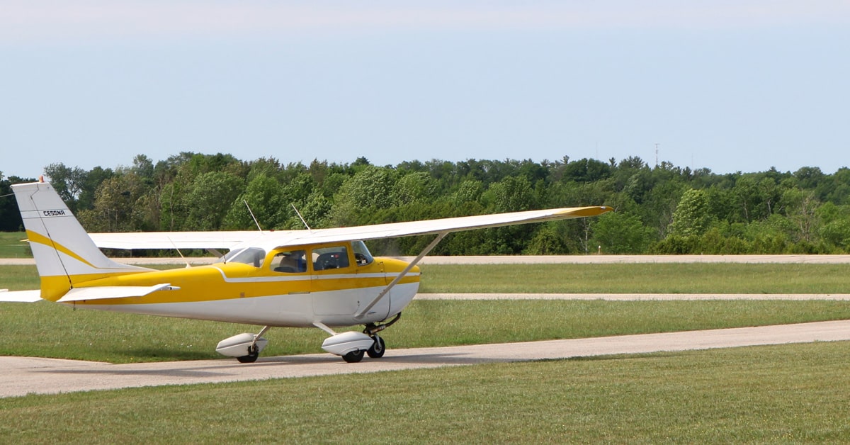
Feature image by Cjp24, CC BY-SA 4.0 https://creativecommons.org/licenses/by-sa/4.0, via Wikimedia Commons.