Our CFI is out enjoying the Reno Air Races this week, so today we’ll share a follow up to Monday’s post with another excerpt from Aerodynamics for Aviators.
Descending a light propeller-driven general aviation aircraft is a fairly simple task. Reduce power to a point where there is more power required than power available, and the basic principle of weight takes over. Under normal flight conditions, descending flight is initiated by the pilot creating a decrement of power (more power required than available). Once the aircraft begins descending, the weight vector can be broken up into two parts, just like with the climb. One component acts perpendicular to the flightpath (down), the other acts forward and parallel to the flightpath, helping accelerate the aircraft.
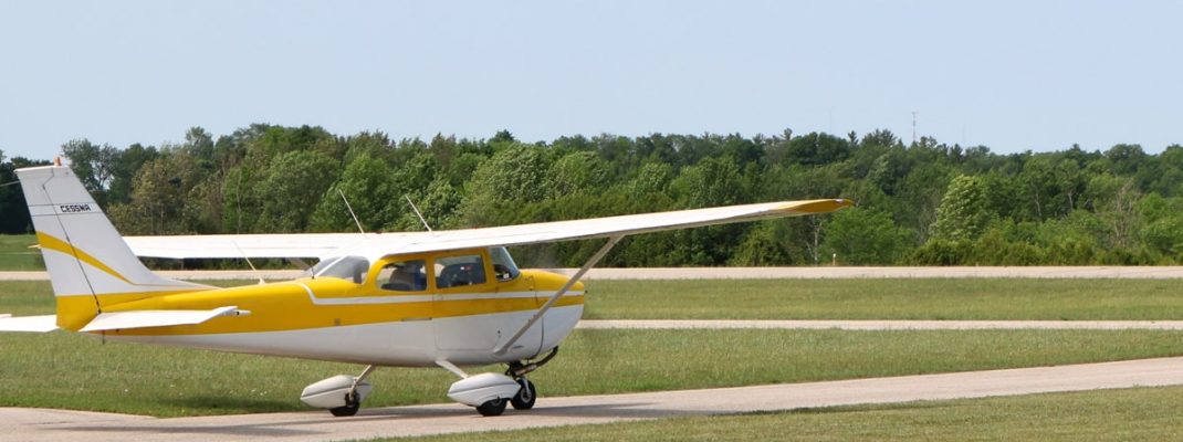
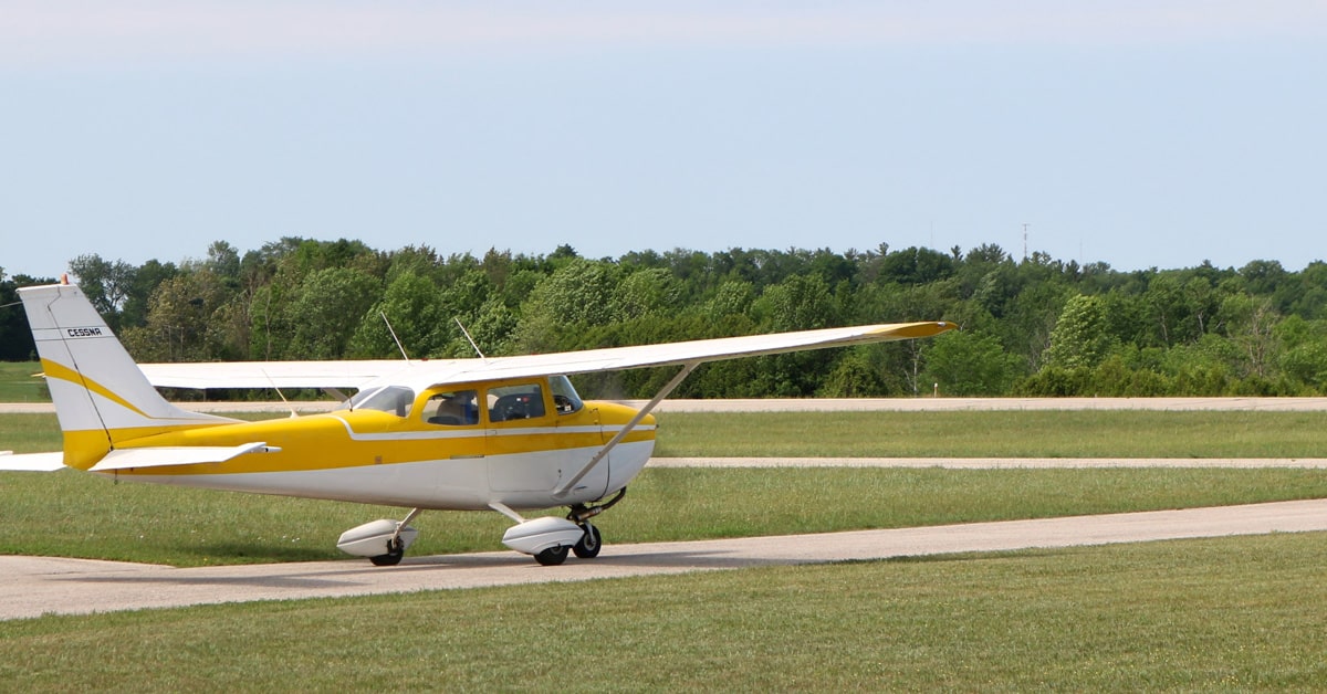
Gliding flight can be self-induced by bringing the power back to idle, but in most piston aircraft, descents are not conducted at idle power, thus they are called a powered descent. This is because of shock cooling and the possible damage it could cause to the engine. A true gliding descent would be used if the engine fails. Gliding flight can be broken down into two parts, minimum sink and maximum range.
The minimum sink glide is used to prolong the time aloft in the event the engine or engines fail. This is a speed that is not published, but could be useful if you are over your current landing site and wish to stay aloft a little longer. Most light single-engine airplanes will be at (or close to) minimum sink with full aft trim. This is slower than best glide speed. A pilot who elects to use this method should accelerate to best glide once a normal pattern altitude is reached. This will provide a larger margin above stall and the aircraft will have more positive maneuverability. It should be noted that the best glide speed should be used unless the pilot has training and experience flying at the minimum sink glide speed.
The maximum glide range occurs at the speed for maximum range: L/DMAX. This is generally a published speed and is used when the engine stops or fails in flight. Some Airplane Flying Manuals (AFMs) contain glide ratio charts. There are some concerns with these charts:
- They do not account for wind.
- They are usually calculated in a minimum drag configuration (gear and flaps up).
- They are usually calculated with controllable-pitch propellers in the full decrease position (high AOA).
- They are usually calculated at maximum gross weight.
Wind is a factor in glide distance and angle. A headwind will decrease glide distance, and the angle of descent will increase (steepen). A tailwind will increase the glide distance and flatten the angle of descent. You experience the effects of both a headwind and a tailwind when you do a power-off approach. On downwind the aircraft has a flatter descent and a higher groundspeed. Turning base to final, the angle of descent steepens and the groundspeed slows.
Weight is also a factor in glide distance if L/DMAX is not maintained. Without an AOA indicator, the only way to maintain a specific AOA at L/DMAX is to vary the airspeed. As weight increases, the airspeed would need to be increased to maintain L/DMAX.
Altitude also affects the airplane’s gliding distance. To understand this we need to step back and look at the effects of altitude on true airspeed. As the aircraft climbs, TAS increases about 2% per 1,000 feet. An aircraft gliding at higher altitudes will have a higher TAS, this means that it will be moving down the slope at a faster rate. This is of particular importance when operating an aircraft at high density altitudes.


