Today we’re focusing on your airplane’s turn and slip indicator. This instrument shows the rotation around the yaw axis (via the ball) and around the roll axis (the miniature airplane or needle), and can be used to establish and maintain a standard-rate turn (3° per second, or a complete circle in two minutes). Today’s post comes from the twelfth edition of Bob Gardner’s The Complete Private Pilot.
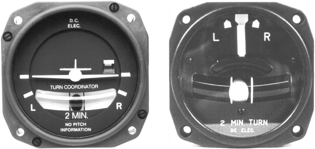
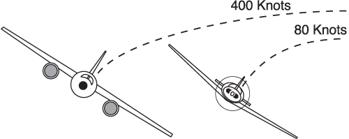
Unlike the turn needle, the turn coordinator is designed so that it reflects roll rate as well as turn rate. Neither instrument indicates bank angle. Bank angle, turn rate, and airspeed are interrelated, as shown in the figure below. For a given bank angle, the rate of turn increases as the airspeed decreases. Consider a light trainer and a jet, both banked 20°: the trainer would complete a 360° turn in a much shorter time than the jet and with a much smaller radius. If both airplanes maintained a 3° per second turn rate, they would both complete the circle at the same time—but the jet would be at an extreme bank angle. The bank angle for a 3° per second turn is approximately 15 percent of the true airspeed, so the trainer at 80 knots would bank 12°, while the jet at 400 knots would have to bank 60°.
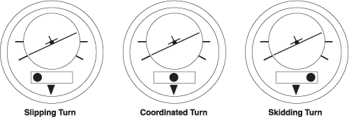
The ball indicates the quality of the turn, with respect to rudder-aileron coordination. The force that causes an airplane to turn is the horizontal component of lift, which is opposed by centrifugal force. If the rate of turn is too great for the angle of bank, centrifugal force is greater than the horizontal component of lift, and the ball rolls toward the outside of the turn. This is termed a “skidding” turn, and either a steeper bank angle (increasing horizontal component) or less rudder pressure on the inside of the turn (reduced centrifugal force) will return the ball to the center. The reverse situation has the ball falling to the inside of the turn in a “slip,” caused by too little centrifugal force and too much horizontal component.
Less bank angle or more inside rudder will return the ball to the center when slipping. A rule of thumb is to “step on the ball”—apply pressure to the rudder pedal on the side of the instrument that the ball is on.
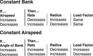
The table below illustrates how various elements of a turn are affected if either bank angle or airspeed is kept constant. For example, with a constant bank angle, an increase in airspeed will decrease the rate of turn while increasing the turn radius; the load factor would not be affected.
Glass cockpit displays do not have the familiar ball, but combine it with the triangular turn index at the top of the heading indicator in the form of a line parallel to the base of the triangle; if the line slides away from the triangle, indicating lack of coordination, just “step on it” with rudder pressure to move it to its proper location.
Featured image by Baptiste Maltaverne from Pixabay.