This week we’re looking again at flight instruments. More specifically, gyroscopic instruments. Take a look at what we’ve posted so far on flight instruments, including our CFI’s series on pitot-static systems. This post is excerpted from Bob Gardner’s The Complete Private Pilot.
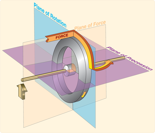
The attitude indicator, the turn indicator, and the directional gyro or heading indicator operate on the principle of gyroscopic rigidity in space. A spinning body, such as a bicycle wheel, will maintain its position in space as long as a rotational force is applied—riding your bike “no hands” is an example of this. Precession, or turning, occurs when any external force is applied to the spinning body, which will react as though the force has been applied at a point 90° away in the direction of rotation. If you lean your bicycle to the right, the turning force is as though pressure has been applied to the left front of the wheel—90° in the direction of rotation. Actually turning the wheel to the right may cause the bicycle to topple over to the right, again the result of gyroscopic precession.
For the foreseeable future, questions about the gyroscopic instruments on your knowledge exam will be based on mechanical gyros—those that have an actual metal disk being driven by either air passing over vanes or an electric motor. The bicycle example is easy to visualize and demonstrate in the classroom.
Gyroscopic “instruments” in this modern age are displayed on a screen, and their inputs come from solid-state devices that deal in forms of mass that it is hard to get our brains around. The most accurate (and expensive) of these is the laser-ring gyro that makes use of interference between multiple lasers; less expensive but least accurate are devices using MEMs (micro-electro-mechanical). A MEM might be as simple as a vibrating crystal…try to visualize the mass being detected in that situation. The whole package, consisting of MEM gyroscopes, accelerometers, and magnetometers, is called an Attitude and Heading Reference System (AHRS). An Air Data Computer can be added, providing airspeed, outside air temperature, actual winds aloft, etc.
The errors inherent in mechanical gyroscopes still exist in solid-state devices, but they are small, constantly monitored internally, and easily corrected without any action on the pilot’s part. If the system detects an anomaly it simply blacks out the display screen or displays a big red X.
As always, our CFI will return on Thursday.
Featured image by Baptiste Maltaverne from Pixabay.