In March we looked at the basics of how an internal combustion works. Your airplane’s engine is a four-cycle engine: on the intake stroke, a fuel/air mixture is drawn into the cylinder as the piston moves down; the mixture is then compressed on an upward piston stroke; a spark ignites the mixture driving the piston down; and finally, the piston rises again pushing the burned gasses out of the exhaust valve. Because your aircraft engine has at least four cylinders, each igniting at a different time, there is always one piston on a power stroke and the process is continuous. Today, we’ll look more closely at the fuel induction system which brings in outside air, mixes it with fuel, and delivers the fuel/air mixture to the cylinder. This post and images come from the Pilots Handbook of Aeronautical Knowledge.
Two types of induction systems are commonly used in small aircraft engines:
- The carburetor system, which mixes the fuel and the air in the carburetor before this mixture enters the intake manifold.
- The fuel injection system, which mixes the fuel and air immediately before entry into each cylinder or injects fuel directly into each cylinder.
Carburetor System
Carburetors are classified as either float type or pressure type. The float type of carburetor, complete with idling, accelerating, mixture control, idle cutoff, and power enrichment systems is probably the most common of all carburetor types. Pressure carburetors are usually not found on small aircraft. The basic difference between a float-type and a pressure-type carburetor is the delivery of fuel. The pressure-type carburetor delivers fuel under pressure by a fuel pump.
In the operation of the float-type carburetor system, the outside air first flows through an air filter, usually located at an air intake in the front part of the engine cowling. This filtered air flows into the carburetor and through a venturi, a narrow throat in the carburetor. When the air flows through the venturi, a low-pressure area is created, which forces the fuel to flow through a main fuel jet located at the throat. The fuel then flows into the airstream where it is mixed with the flowing air.
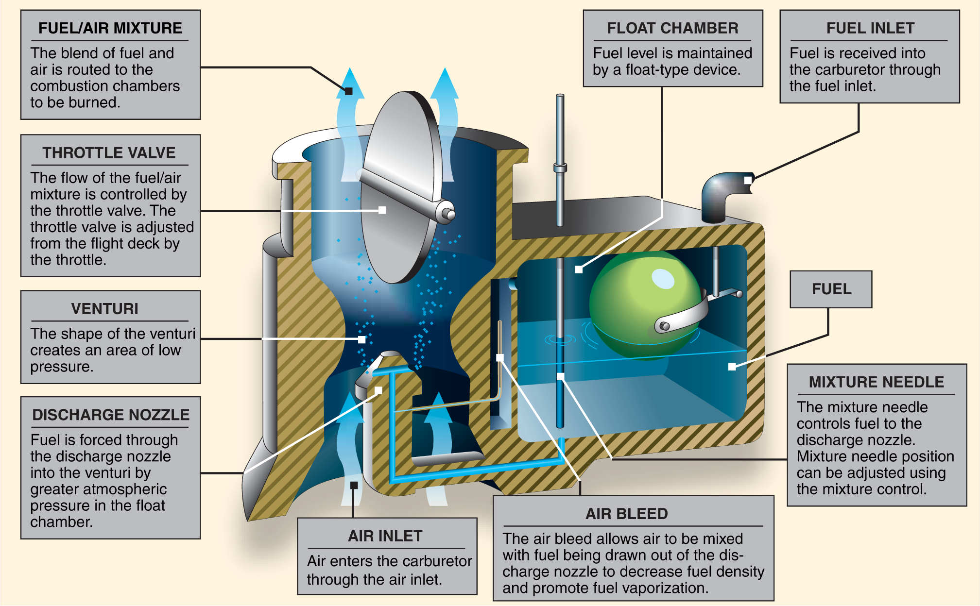
The fuel/air mixture is then drawn through the intake manifold and into the combustion chambers where it is ignited. The float-type carburetor acquires its name from a float, which rests on fuel within the float chamber. A needle attached to the float opens and closes an opening at the bottom of the carburetor bowl. This meters the correct amount of fuel into the carburetor. The flow of the fuel/air mixture to the combustion chambers is regulated by the throttle valve, which is controlled by the throttle in the flight deck.
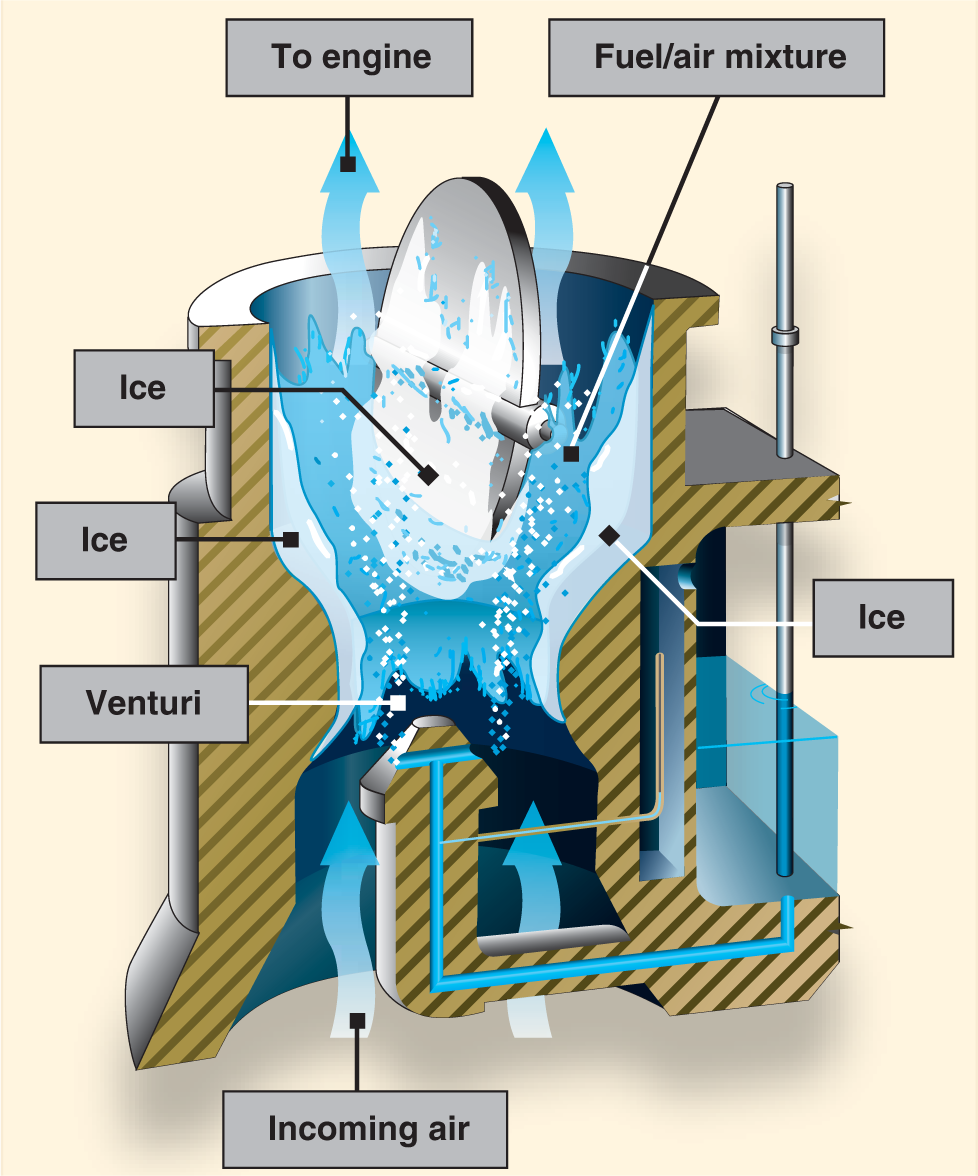
The chief disadvantage of the float carburetor, however, is its icing tendency. Since the float carburetor must discharge fuel at a point of low pressure, the discharge nozzle must be located at the venturi throat, and the throttle valve must be on the engine side of the
discharge nozzle. This means the drop in temperature due to fuel vaporization takes place within the venturi. As a result, ice readily forms in the venturi and on the throttle valve. If water vapor in the air condenses when the carburetor temperature is at or below freezing, ice may form on internal surfaces of the carburetor, including the throttle valve.
Fuel Injection Systems
In a fuel injection system, the fuel is injected directly into the cylinders, or just ahead of the intake valve. The air intake for the fuel injection system is similar to that used in a carburetor system, with an alternate air source located within the engine cowling. This source is used if the external air source is obstructed. The alternate air source is usually operated automatically, with a backup manual system that can be used if the automatic feature malfunctions.
A fuel injection system usually incorporates six basic components: an engine-driven fuel pump, a fuel/air control unit, fuel manifold (fuel distributor), discharge nozzles, an auxiliary fuel pump, and fuel pressure/flow indicators.
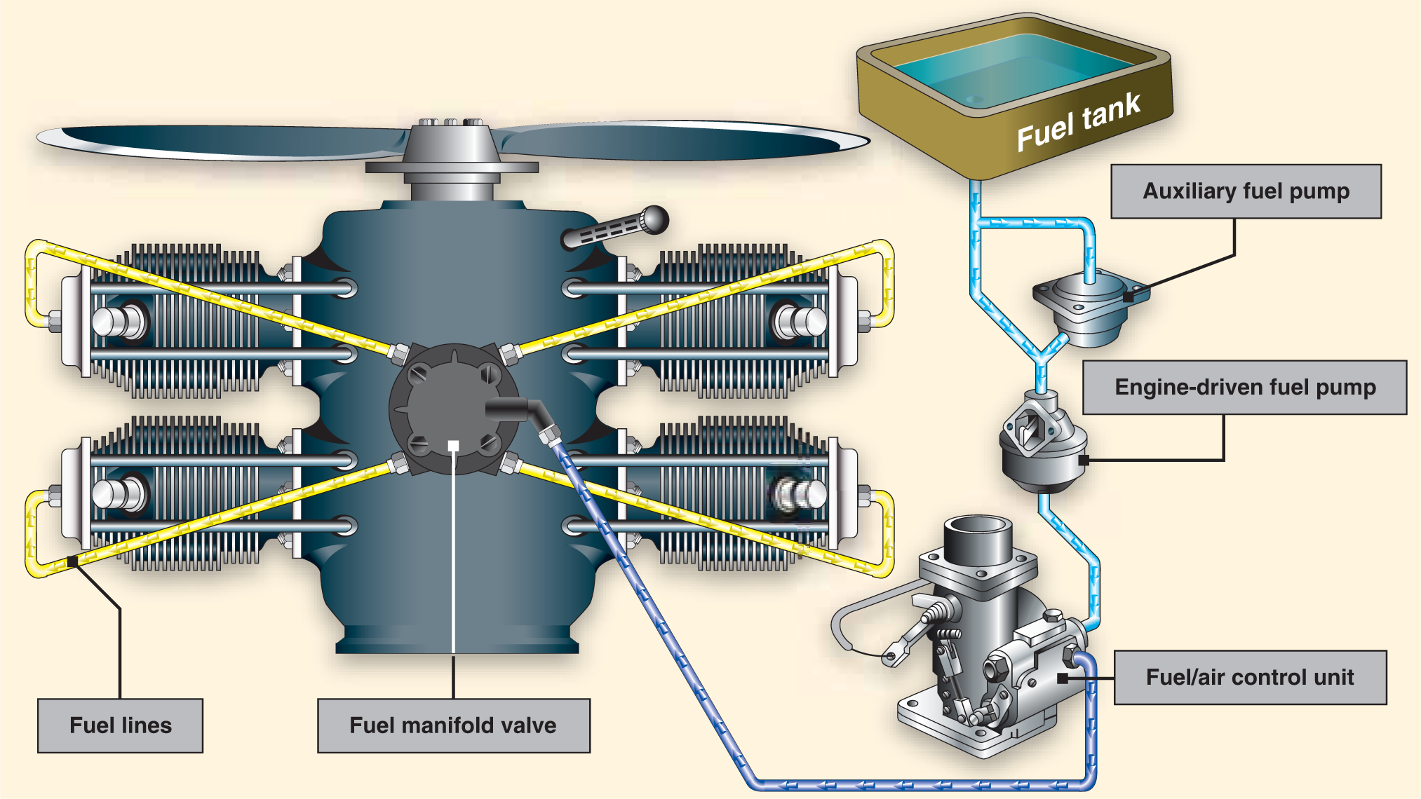
The auxiliary fuel pump provides fuel under pressure to the fuel/air control unit for engine starting and/or emergency use. After starting, the engine-driven fuel pump provides fuel under pressure from the fuel tank to the fuel/air control unit.
This control unit, which essentially replaces the carburetor, meters fuel based on the mixture control setting, and sends it to the fuel manifold valve at a rate controlled by the throttle. After reaching the fuel manifold valve, the fuel is distributed to the individual fuel discharge nozzles. The discharge nozzles, which are located in each cylinder head, inject the fuel/air mixture directly into each cylinder intake port.
A fuel injection system is considered to be less susceptible to icing than the carburetor system, but impact icing on the air intake is a possibility in either system. Impact icing occurs when ice forms on the exterior of the aircraft, and blocks openings such as the air intake for the injection system.
Disadvantages of a fuel injection system include difficulty starting a hot engine, vapor lock during ground operations on hot days, and problems associated with restarting an engine that has quit due to fuel starvation.
We’ll have more on Thursday from our very own CFI.
Featured image by KissShot at adobe stock.com.