Before reading today’s post, go back and re-read our post on airplane stability from earlier this month. As promised, we’ll talk today about how static and dynamic stability applies to you as a pilot. We’ll pick up where we left off in Bill Kershner’s The Advanced Pilot’s Flight Manual.
The elevators control the pitch (the movement around the lateral axis). The pilot’s ability to control the airplane about this axis is very important. In designing an airplane, a great deal of effort is spent in making it stable around all three axes. But longitudinal stability (stability about the pitch axis) is considered to be the most affected by variables introduced by the pilot, such as airplane loading.
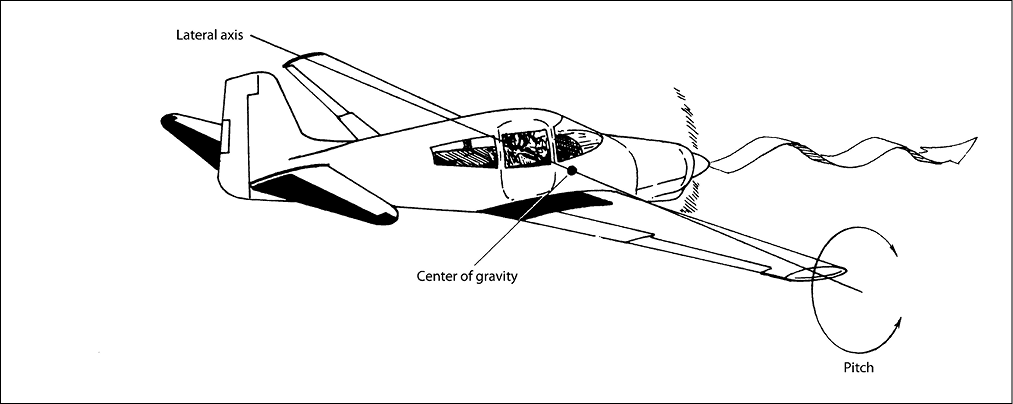
Figure 1. The elevators control movement about the lateral axis (pitch).
Take a look at an airplane in balanced, straight and level flight (Figure 2). Making calculations from the center of gravity (CG), you find the moment (force × distance) about the CG caused by the wing’s lift is 5 × 3,100 or 15,500 lb-in. This is a nose-down moment. To maintain straight and level flight there must be an equal moment in the opposite direction or the airplane would be attempting to do an outside loop. This opposite moment is furnished by a down force on the tail. Its moment must be 15,500 lb-in. in a tail-down direction. The distance shown from the CG to the center of tail lift is 155 inches; therefore the down force at the tail must be 100 pounds (force × distance = 100 pounds × 155 inches). The tail-down moment is also 15,500 lb-in., which balances the nose-down moment. The airplane is statically balanced.
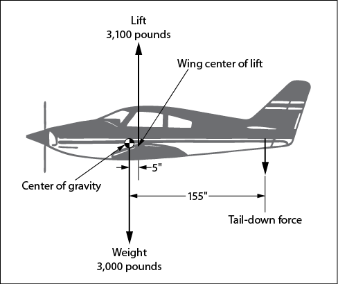
Figure 2. Airplane in balanced straight-and-level flight.
In order for the airplane to maintain level flight, the upward forces must balance the downward forces.
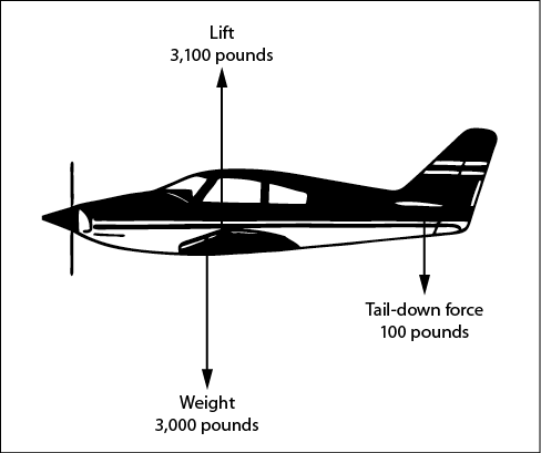
Figure 3. Summation of vertical forces: total up force 3,100 pounds and total down force 3,100 pounds; forces balanced.
The down forces are the airplane’s weight (3,000 pounds) and the tail-down force (100 pounds), which total 3,100 pounds. In order to balance this, the up force (lift) must be 3,100 pounds. The wing itself contributes some pitching effects.
For airplanes with fixed, or nonadjustable, stabilizers, the stabilizer is set by the manufacturer at an angle that furnishes the correct down force at the expected cruising speed and CG position.
The tail-down force is the result of propeller slipstream, downwash from the wing, and the free-stream velocity (airspeed).
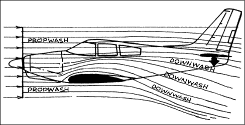
Figure 4. Factors contributing to the tail-down force.
Suppose you’re flying straight and level (hands-off) at the design cruise speed and power setting and suddenly close the throttle. The slipstream force suddenly drops to practically nothing; the airplane starts slowing as thrust is no longer equal to drag, and the free-stream velocity also drops. You’ve suddenly lost some of the tail-down force. The result is that the nose drops. This is a healthy situation; the airplane is trying to pick up speed and reestablish the balance.
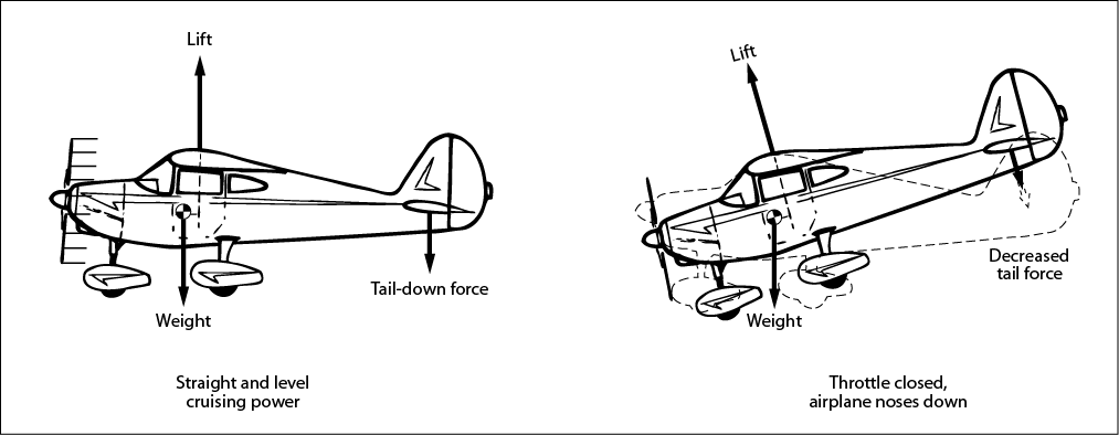
Figure 5.
Of course, as the airplane slows, lift decreases and the airplane starts to accelerate downward for a very short time, but this is not so noticeable to you as the nosing-down action.
We’ll disregard the airplane settling and think only in terms of the rotational movement caused by closing the throttle. One way of looking at it is to return to the seesaw of your earlier days. When the kid on the other end suddenly jumped off you set up your own “nose down” (the moments were no longer balanced).
You set the desired tail force for various airspeeds by either holding fore or aft wheel pressure or setting the elevator trim. If you are trimmed for straight and level flight, closing the throttle requires more up-elevator trim if you want to glide hands-off at the recommended glide speed. A propeller-driven airplane will always require less up-elevator trim for a given airspeed when using power than when in power-off conditions. You can see this for yourself the next pretty day when you’re out just flying around. Trim the airplane to fly straight and level at the recommended glide speed and use whatever power is necessary to maintain altitude. Then close the throttle and keep your hands off the wheel. You’ll find that the airspeed is greater in the power-off condition—the airplane’s nose drops until it picks up enough free-stream velocity to compensate for the loss of slipstream. This may be up to about cruise speed, depending on the airplane.
The arrangement of having the CG ahead of the center of lift, and an aerodynamic tail-down force, results in the airplane always trying to return to a safe condition. Pull the nose up and the airplane slows and the tail-down force decreases. The nose will soon drop unless you retrim it or hold it up with increased back pressure. Push the nose down and it wants to come back up as the airspeed increases the tail-down force. The stable airplane wants to remain in its trimmed conditions, and this inherent (built-in) stability has gotten a lot of pilots out of trouble.
A lifting tail is necessary on this airplane in order to maintain balance. From a purely aerodynamic standpoint, the two lifting surfaces (wing and tail) are a good idea; from a stability standpoint, this type of configuration is not so good.
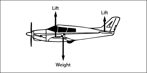
Figure 6. A different loading and tail force.
When you throttle back, the tail lift decreases and the nose tends to go up! This is not conducive to easy pilot control. The engineers would rather have a little less aerodynamic efficiency and more stability. So this arrangement is avoided—although it is not nearly as critical in a jet airplane. Actually, in some conditions (high CL, a tail upload may be present, even for the “standard” airplane that has a tail-down force at cruise.
The canard (horizontal-tail-first) designs have appeared again in the past few years. Some of these airplanes are quite efficient because both the wings and horizontal tail are lifting, versus the more conventional arrangement in Figure 3. One advantage of the canard-type is that it is stall and spin resistant if the forward surface is designed to lose its lift (and pitch the nose down to decrease the angle of attack of the main wing before it reaches the critical angle). The canard arrangement is not new (see photos of the Wright brothers’ first powered flight), but the state of the art has improved so much that the newer designs are making a strong impact on the industry.
Check back for more on Thursday from our CFI. ASA will be closed on Monday for the Fourth of July. Thanks for reading the Learn to Fly Blog!