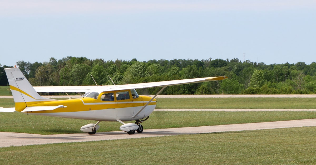
Back to basics today on the Learn to Fly Blog: your propeller. The aircraft propeller consists of two or more blades and a central hub to which the blades are attached. Each blade of an aircraft propeller is essentially a rotating wing, and thus the blades act like airfoils producing thrust. Today’s post comes from the Pilot’s Handbook of Aeronautical Knowledge.
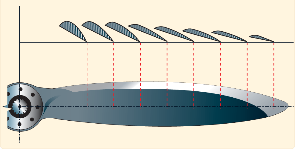
A cross-section of a typical propeller blade is shown in figure 1. This section or blade element is an airfoil comparable to a cross-section of an aircraft wing. One surface of the blade is cambered or curved, similar to the upper surface of an aircraft wing, while the other surface is flat like the bottom surface of a wing. The chord line is an imaginary line drawn through the blade from its leading edge to its trailing edge. As in a wing, the leading edge is the thick edge of the blade that meets the air as the propeller rotates.
Figure 1. Airfoil sections of propeller blade.
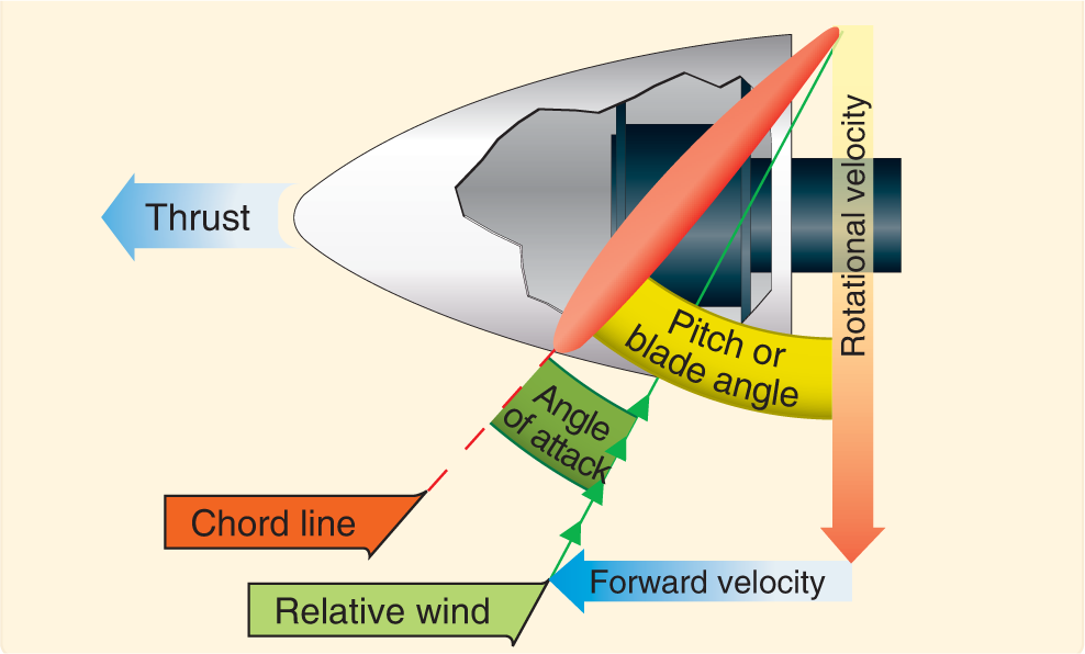
Blade angle, usually measured in degrees, is the angle between the chord of the blade and the plane of rotation and is measured at a specific point along the length of the blade. Because most propellers have a flat blade “face,” the chord line is often drawn along the face of the propeller blade. Pitch is not blade angle, but because pitch is largely determined by blade angle, the two terms are often used interchangeably. An increase or decrease in one is usually associated with an increase or decrease in the other.
Figure 2. Propeller blade angle.
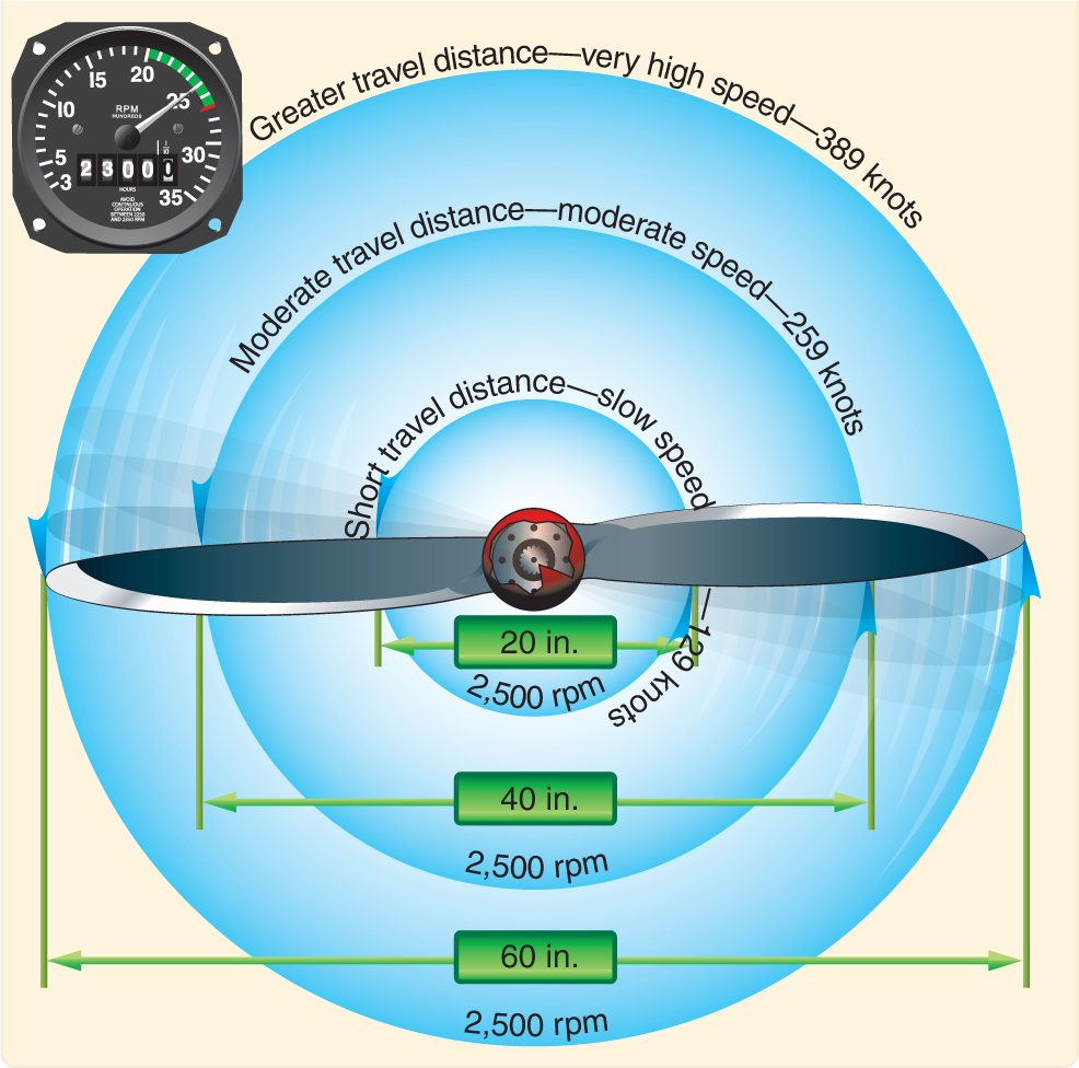
The pitch of a propeller may be designated in inches. A propeller designated as a “74-48” would be 74 inches in length and have an effective pitch of 48 inches. The pitch is the distance in inches, which the propeller would screw through the air in one revolution if there were no slippage. When specifying a fixed-pitch propeller for a new type of aircraft, the manufacturer usually selects one with a pitch that operates efficiently at the expected cruising speed of the aircraft. Every fixed-pitch propeller must be a compromise because it can be efficient at only a given combination of airspeed and revolutions per minute (rpm). Pilots cannot change this combination in flight.
When the aircraft is at rest on the ground with the engine operating, or moving slowly at the beginning of takeoff, the propeller efficiency is very low because the propeller is restrained from advancing with sufficient speed to permit its fixed-pitch blades to reach their full efficiency. In this situation, each propeller blade is turning through the air at an AOA that produces relatively little thrust for the amount of power required to turn it.
To understand the action of a propeller, consider first its motion, which is both rotational and forward. As shown by the vectors of propeller forces in figure 2, each section of a propeller blade moves downward and forward. The angle at which this air (relative wind) strikes the propeller blade is its AOA. The air deflection produced by this angle causes the dynamic pressure at the engine side of the propeller blade to be greater than atmospheric pressure, thus creating thrust. The shape of the blade also creates thrust because it is cambered like the airfoil shape of a wing. As the air flows past the propeller, the pressure on one side is less than that on the other. As in a wing, a reaction force is produced in the direction of the lesser pressure. The airflow over the wing has less pressure, and the force (lift) is upward. In the case of the propeller, which is mounted in a vertical instead of a horizontal plane, the area of decreased pressure is in front of the propeller, and the force (thrust) is in a forward direction. Aerodynamically, thrust is the result of the propeller shape and the AOA of the blade.
Thrust can be considered also in terms of the mass of air handled by the propeller. In these terms, thrust equals mass of air handled multiplied by slipstream velocity minus velocity of the aircraft. The power expended in producing thrust depends on the rate of air mass movement. On average, thrust constitutes approximately 80 percent of the torque (total horsepower absorbed by the propeller). The other 20 percent is lost in friction and slippage. For any speed of rotation, the horsepower absorbed by the propeller balances the horsepower delivered by the engine. For any single revolution of the propeller, the amount of air handled depends on the blade angle, which determines how big a “bite” of air the propeller takes. Thus, the blade angle is an excellent means of adjusting the load on the propeller to control the engine rpm.
The blade angle is also an excellent method of adjusting the AOA of the propeller. On constant-speed propellers, the blade angle must be adjusted to provide the most efficient AOA at all engine and aircraft speeds. Lift versus drag curves, which are drawn for propellers, as well as wings, indicate that the most efficient AOA is small, varying from +2° to +4°. The actual blade angle necessary to maintain this small AOA varies with the forward speed of the aircraft.
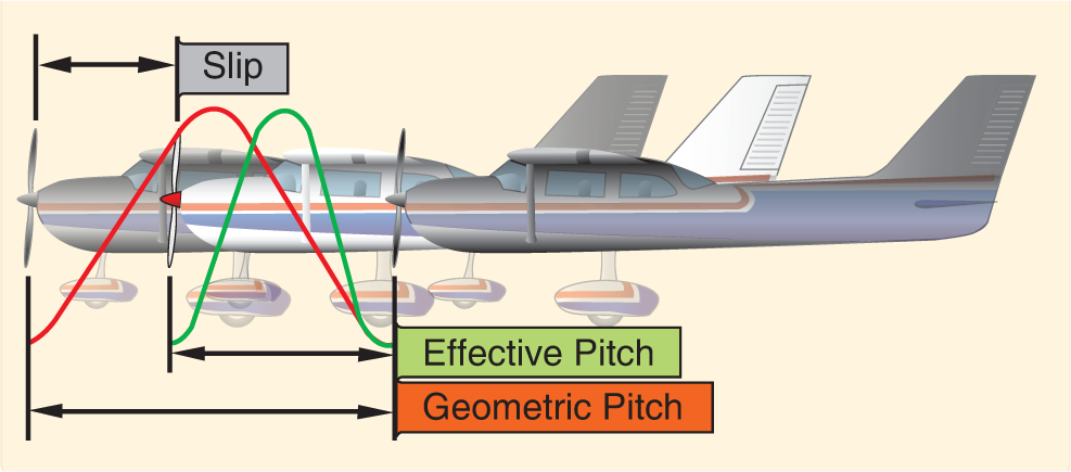
Fixed-pitch and ground-adjustable propellers are designed for best efficiency at one rotation and forward speed. They are designed for a given aircraft and engine combination. A propeller may be used that provides the maximum efficiency for takeoff, climb, cruise, or high-speed flight. Any change in these conditions results in lowering the efficiency of both the propeller and the engine. Since the efficiency of any machine is the ratio of the useful power output to the actual power input, propeller efficiency is the ratio of thrust horsepower to brake horsepower. Propeller efficiency varies from 50 to 87 percent, depending on how much the propeller “slips.” Propeller slip is the difference between the geometric pitch of the propeller and its effective pitch. Geometric pitch is the theoretical distance a propeller should advance in one revolution; effective pitch is the distance it actually advances. Thus, geometric or theoretical pitch is based on no slippage, but actual or effective pitch includes propeller slippage in the air.
Figure 3. Propeller slippage.
The reason a propeller is “twisted” is that the outer parts of the propeller blades, like all things that turn about a central point, travel faster than the portions near the hub. If the blades had the same geometric pitch throughout their lengths, portions near the hub could have negative AOAs while the propeller tips would be stalled at cruise speed. Twisting or variations in the geometric pitch of the blades permits the propeller to operate with a relatively constant AOA along its length when in cruising flight. Propeller blades are twisted to change the blade angle in proportion to the differences in speed of rotation along the length of the propeller, keeping thrust more nearly equalized along this length.
Figure 4. Propeller tips travel faster than the hub.
Usually 1° to 4° provides the most efficient lift/drag ratio, but in flight the propeller AOA of a fixed-pitch propeller varies—normally from 0° to 15°. This variation is caused by changes in the relative airstream, which in turn results from changes in aircraft speed. Thus, propeller AOA is the product of two motions: propeller rotation about its axis and its forward motion.
A constant-speed propeller automatically keeps the blade angle adjusted for maximum efficiency for most conditions encountered in flight. During takeoff, when maximum power and thrust are required, the constant-speed propeller is at a low propeller blade angle or pitch. The low blade angle keeps the AOA small and efficient with respect to the relative wind. At the same time, it allows the propeller to handle a smaller mass of air per revolution. This light load allows the engine to turn at high rpm and to convert the maximum amount of fuel into heat energy in a given time. The high rpm also creates maximum thrust because, although the mass of air handled per revolution is small, the rpm and slipstream velocity are high, and with the low aircraft speed, there is maximum thrust.
After liftoff, as the speed of the aircraft increases, the constant speed propeller automatically changes to a higher angle (or pitch). Again, the higher blade angle keeps the AOA small and efficient with respect to the relative wind. The higher blade angle increases the mass of air handled per revolution. This decreases the engine rpm, reducing fuel consumption and engine wear, and keeps thrust at a maximum. After the takeoff climb is established in an aircraft having a controllable-pitch propeller, the pilot reduces the power output of the engine to climb power by first decreasing the manifold pressure and then increasing the blade angle to lower the rpm.
At cruising altitude, when the aircraft is in level flight and less power is required than is used in takeoff or climb, the pilot again reduces engine power by reducing the manifold pressure and then increasing the blade angle to decrease the rpm. Again, this provides a torque requirement to match the reduced engine power. Although the mass of air handled per revolution is greater, it is more than offset by a decrease in slipstream velocity and an increase in airspeed. The AOA is still small because the blade angle has been increased with an increase in airspeed.
Featured image by TarikVision at stock.adobe.com.