Today, we’re sharing an excerpt from The Pilot’s Manual: Instrument Flying. This post is a follow-up to last month’s IFR: The Instrument Landing System (ILS).
To assist pilots transitioning to a visual landing at the conclusion of a precision instrument approach, precision instrument runways have specific markings.
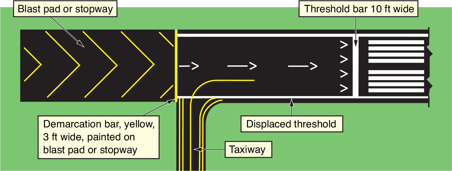
A displaced threshold on an instrument runway is indicated by arrows in the middle of the runway leading to the displaced threshold mark. The runway edge lights to the displaced threshold appear red to an airplane on approach, and to an airplane taxiing to the displaced threshold from the absolute end of the runway. They appear white when taxiing back from the displaced threshold toward the absolute end of the runway. The green runway end lights seen on approach to a runway with a displaced threshold are found off the edge of the runway.
The runway surface with arrows to the displaced threshold is available for taxiing, takeoff and landing roll-out, but not for landing. The initial part of this runway is a non-touchdown area. If chevrons rather than arrows are used to mark the displaced threshold, then the surface is not available for any use, other than aborted takeoff from the other direction.
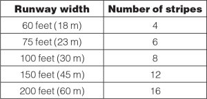
A precision instrument runway will contain a designation, centerline, threshold, aiming point, touchdown zone, and side strips as seen in the figure below. Runway threshold strips can be configured in two ways. Four solid strips on either side of the centerline or configured as such that the number of strips correlates to the width of the runway (see table). The runway aiming point markers are large rectangular marks on each side of the runway centerline usually placed 1,000 feet after the threshold and serve as a visual aiming point for the pilot. Touchdown zone markers identify the touchdown zone for landing operations, providing coded distance information in 500 foot intervals and shown as either one, two, or three vertical stripes on either side of the centerline.


