The airspeed indicator (ASI) is an important component of the pitot-static instruments. As you can imagine, there are numerous speeds for each aircraft. It can be tough sometimes to remember all those V-speeds, particularly if you are transitioning between multiple aircraft with different performance characteristics.
The ASA Dictionary of Aeronautical Terms by Dale Crane defines V-speeds as a series of designators used by the FAA and listed in 14 CFR 1 to describe certain flight conditions. For example, the aircraft’s stalling speed, or minimum steady flight speed at which the airplane is controllable, is designated as VS. The ASI is designed to allow for easy reference of certain airspeed limitations that are important to the safe operation of the aircraft. This is accomplished by using a standard color-coded marking system and is required on all ASI installed in aircraft weighing less than 12,500 pounds manufactured after 1954. Let’s break it down so you understand fully how to interpret the ASI.
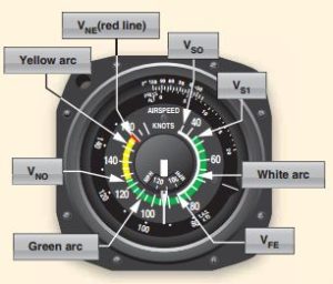
WHITE ARC—This is known as the flap operating range, or the speed at which the aircraft can be flown with full flaps. The lower limit represents VSO, the stalling speed or minimum steady flight speed in the landing configuration. The upper limit represents VFE, the maximum speed with the flaps extended.
GREEN ARC—Normal operating range of the aircraft, the speeds at which most flying occurs. Lower limit represents VS1, the stalling speed or minimum steady flight speed in a specified configuration. Upper limit represents VNO, the maximum structural cruising speed.
YELLOW ARC—This is the caution range, flight at these speeds should only be conducted in smooth air.
RED RADIAL LINE—Operating above this speed is prohibited, my cause structural damage or failure.
Not all V-speed can be found on the ASI. Other speeds important to flight may be found on placards within the aircraft, in the aircraft Pilots Operating Handbook (POH), or in the Airplane Flight Manual (AFM). It’s important to understand how to interpret the ASI color-coded system and know what each limit represents. The FAA knowledge exam includes questions on this information.
1. What does the red line on an airspeed indicator represent?
A—Maneuvering speed.
B—Turbulent or rough-air speed.
C—Never-exceed speed.
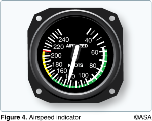
2. (Refer to Figure 4.) Which marking identifies the never-exceed speed?
A—Upper limit of the green arc.
B—Upper limit of the white arc.
C—The red radial line.
3. (Refer to Figure 4.) Which color identifies the power-off stalling speed in a specified configuration?
A—Upper limit of the green arc.
B—Upper limit of the white arc.
C—Lower limit of the green arc.


