This week we’re back with more on IFR. Go back and familiarize yourself with the basics we’ve introduced in earlier introductory posts from this year. Today, we’ll look at instrument scanning techniques. This post features text and images from The Pilot’s Manual Volume 3: Instrument Flying.
In instrument conditions, when the natural horizon cannot be seen, pitch attitude and bank angle information is still available to the pilot in the cockpit from the attitude indicator. The pitch attitude changes against the natural horizon are reproduced in miniature on the attitude indicator.
In straight-and-level flight, for instance, the wings of the miniature airplane should appear against the horizon line, while in a climb they should appear one or two bar widths above it.
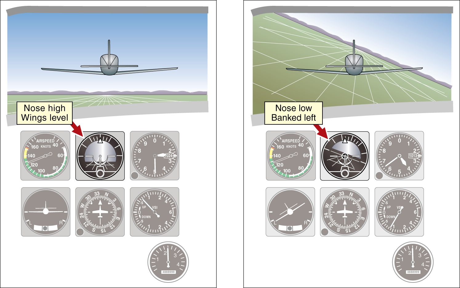
In a turn, the wing bars of the miniature airplane will bank along with the real airplane, while the horizon line remains horizontal. The center dot of the miniature airplane represents the airplane’s nose position relative to the horizon. Today, there are a variety of attitude indicators you might see. Some are referred to as a primary flight display (PFD). In any display, the principles remain the same: the center dot or center point’s position relative to the horizon indicates a climb or descent.
Scanning the instruments with your eyes, interpreting their indications and applying this information is a vital skill to develop if you are to become a good instrument pilot. Power is selected with the throttle, and can be checked (if required) on the power indicator. Pitch attitude and bank angle are selected using the control column, with frequent reference to the attitude indicator. With both correct power and attitude set, the airplane will perform as expected. The attitude indicator and the power indicator, because they are used when controlling the airplane, are known as the control instruments. The actual performance of the airplane, once its power and attitude have been set, can be cross-checked on what are known as the performance instruments—the altimeter for altitude, the airspeed indicator for airspeed, the heading indicator for direction, and so on.
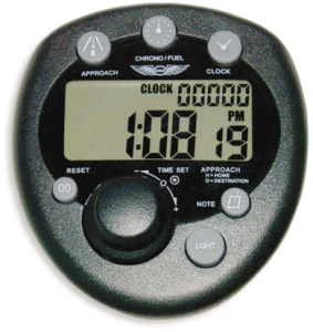
A valuable instrument, important in its own right, is the clock or timer. Time is extremely important in instrument flying. The timer is used:
- in holding patterns (which, for example, may be racetrack patterns with legs of 1 or 2 minutes duration);
- in timed turns (a 180° change of heading at standard-rate of 3° per second taking 60 seconds); and
- to measure time after passing certain radio fixes during instrument approaches (at 90 knots groundspeed, for instance, it would take 2 minutes to travel the 3 NM from a particular fix to the published missed approach point).
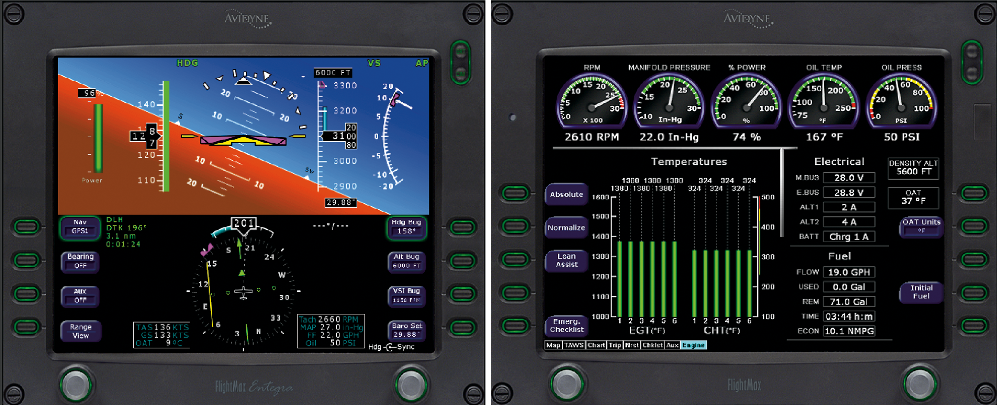
Another area on the instrument panel contains the navigation instruments, which indicate the position of the airplane relative to selected navigation facilities. These NAVAIDs will be considered in detail later in your training, but the main ones are:
- VHF omni range (VOR) cockpit indicator, which indicates the airplane’s position relative to a selected course to or from the VOR ground station;
- automatic direction finder (ADF), which has a needle that points to a nondirectional beacon (NDB); and
- distance measuring equipment (DME) or VORTAC, which indicates the slant distance in nautical miles to the selected ground station.
Instrument scanning is an art that will develop naturally during your training, especially when you know what to look for. The main scan to develop initially is that of the six basic flight instruments, concentrating on the AI and radiating out to the others as required. Then as you move on to en route instrument flying, the navigation instruments will be introduced. Having scanned the instruments, interpreted the message that they contain, built up a picture of where the airplane is and where it is going, you can now control it in a meaningful way.
